The Composite Order
The Composite order originated in the work of Alberti and Serlio, in an attempt to account for the large number of antique Roman columns ostensibly Corinthian, but with capitals that did not follow the standard format. The main characteristic of this order is that it can be said to be neither Doric, Ionic nor Corinthian; indeed, the example that became standard (which was used in many triumphal arches, and in the temple of Bacchus and the Baths of Diocletian) is composed of elements from all three orders.
The basic characteristics of the Composite order are that:
- The column height was set by Serlio, who advocated 10 diameters, and was followed by most other authorities (though Scamozzi set his at 9
3/4 diameters to make it shorter than his Corinthian order, which he considered superior) - The base used is usually the one showed as an alternative by Serlio, this one being similar but a little bolder than the Corinthian, especially after its adoption by Vignola for his order
- The shaft is usually treated exactly like that of the Corinthian order
- The capital is the most varied of all the orders, as there is no single native type, though the version combining Ionic and Corinthian leafage became the most common (though Serlio specifically showed alternate capitals combining Doric and Corinthian elements, to show the nature of the work as combining other elements together into one)
- The entablature follows the capital in not having a single type associated with it, though a common example became that adopted by Palladio, featuring a cornice with large dual-staged block-like modillions, he being followed in its usage by Scamozzi, Perrault & Gibbs
The Composite Order of Sir William Chambers
The Composite order illustrated by Chambers is one he devised himself, in which I have attempted to avoid the faults, and unite the perfections, of those abovementioned
.
The cornice of the entablature is imitated from Scamozzi, and differs from the Corinthian, only in the modillions; which are square, and composed of two fascias
.
The general dimensions of this order are exactly the same as for the Corinthian order:
- The column height is 600 min, and the entablature height is 150 min, thus making the order 750 min high.
- The capital is 70 min high and the base is 30 min high, thus making the shaft 500 min high.
- The pedestal is 180 min high, thus making the order with the pedestal 930 min high.
- and, as with all Chambers’ orders, the lower diameter is 60 minutes, and the upper diameter is 50 minutes, making the diminution one-sixth of the column diameter.
Create the Order Profiles
- Start in parallel projection, front view
- Set a guide 30 min to the right of the Centerline (for the lower diameter), and another 11
2/3 min to the right of that (for the projection of the plinth & pedestal die) - Set guides horizontally and vertically on the Origin point
The Pedestal Profiles
- Set a guide 180 min up on the Blue Axis from the Baseline (for the height of the pedestal)
As stated earlier, the Corinthian & Composite Pedestals are the same, so I will forego recreating the profiles here. If you wish you can import the Corinthian profiles, or simply set the guide and insert the finished Pedestal later, as I will do.
The Column Base Profiles
As noted earlier, Chambers uses the Attic base for most of his orders, but again he here offers an alternate base, which will be used instead.
The Composite base Chambers shows is once again derived from Serlio & Vignola, being almost identical to the Corinthian. The only difference between the two being that instead of the central pair of astragals in the Corinthian base, the Composite has a single larger astragal.
- Set guides, going up from the Baseline, for 91
1/2 min, 61/2 min,3/4 min, 21/2 min, 23/4 min, 21/4 min,3/4 min, and 5 min heights (for the heights of the plinth, lower torus, lowest fillet, lower scotia, combined fillets & astragal, upper scotia, highest fillet and upper torus) - Set guides
3/4 min coming inward to the astragal location from the guides setting the combination’s 23/4 min height - Draw a Rectangle the height and projection of the Plinth
- Double-Click the Face just created and make it a Component
Column-Base-Plinth-profile - Set Guides, going out rightwards from the Lower Diameter, for 3
2/3 , 61/3 , and 72/3 min projections (for the Fillet under the Upper Torus, the Upper Torus & Astragal, and Lowest Fillet) - Draw a Torus above the Plinth, going backwards towards the Centerline from the projection of the Plinth
- Draw a Line, from the top Endpoint of the Torus, inwards to the next Guide, then upwards to the next Guide (to form the Lower Torus and Fillet above it)
- Draw the Astragal, going back from the designated Guide (which should be the 2nd to the right of that for the Lower Diameter), then Divide the top rear construction line (representing half the Astragal) into 5 parts, and set a Guide 1 part back from the right, then draw a pair of Lines, going up and down from the top & bottom of the Astragal on that Guide, to the next Guides flanking it, then Erase the construction square (except the parts of it connecting the last two Lines with the curved front)
- Draw a Line, from the Endpoint of the Line coming up from the lower Torus, inwards to the Guide marking the Lower Diameter, then up to the next Guide, then out to the line coming down from the Astragal
- Draw another Line, from the Endpoint of the Line coming up from the top of the Astragal, going inwards to the Lower Diameter, then up to the next Guide, then out to the next Guide (marking the Upper Fillet), then up to the next Guide
- Draw a Torus, using the Guides for the Upper Torus, being sure to keep the connecting line to the Fillet below it
- Draw a Line, from the top Endpoint of the Upper Torus, back to the Centerline, then down to the top of the Plinth, then out to the Endpoint of the Lower Torus
- Double-Click the Face just created and make it a Component
Column-Base-Torii-profile - Replace the two indentations with Scotia moldings
- Erase any Guides below the top of the Base, and to the right of the Lower Diameter
- Set a guide 500 min up from the top of the base (for the height of the shaft)
- Set a guide 2
1/2 min up from the bottom of the shaft (for the lower cincture), and another 31/3 min up from that (for the height of the congé) - Set a guide 3
1/3 min out from the lower diameter (for the lower cincture) - Draw a line, from the top-left corner of the base, out to the guide marking the lower cincture projection, then continue it up to the next guide
- Draw a congé, from the last endpoint, up and in to the guide marking the lower diameter (thus completing the lower cincture of the column)
- Erase the guides to the right of the lower diameter and below the congé just drawn
- Now go back and draw a line, from the top-left corner of the base, up to the guide marking the top of the shaft (forming the column centerline)
- Set guides 3
1/3 and 12/3 min down from the top of the shaft (for the astragal and upper cincture), then another 21/2 min further down (for the height of the congé) - Set a guide 25 min out from the centerline (for the upper diameter)
- Set a guide 2
1/2 min out from the upper diameter (for the upper cincture; the astragal projects to the lower diameter) - Draw a Line from the last endpoint (at the top of the shaft Centerline) outwards to the guide marking the projection of the astragal, then use the endpoint of that line as the start for drawing the astragal, which you will draw going down to the next guide
- Draw a line from the endpoint of the astragal in to the next guide, then down to the next guide
- Draw a congé, from the last endpoint, down and in to the guide marking the upper diameter (thus completing the upper cincture)
- Erase the guides marking the height and projection of the upper cincture & astragal (leaving the guides marking the upper & lower diameters and top of the column shaft)
- Connect the top and bottom congé endpoints by applying entasis to the curve between the two points.
- Double-click the face just created and make it a component
Column-Shaft-profile - Erase any guides to the right of the upper diameter, and below the top of the shaft
- Set a Guide 70 min up from the top of the Shaft (for the height of the Capital)
- Set a construction Guide 100 min above the highest Guide
- Draw a Line, from the intersection of the Column Centerline and the 100 min Guide, going out on the Red Axis, for 60 min
- Using the starting intersection above as the rotation point, Rotate the line just drawn 45 degrees clockwise, then set Guides at its Endpoint below and to the right (forming a square through which the line bisects diagonally), then Rotate/Copy the two Guides 180 degrees (forming the square in which the Abacus plan will be drawn)
- At the bottom Endpoint of the diagonal line, draw a Line, at right angles (or perpendicular) to the diagonal line), for 3
1/4 min on either side (forming the width of the top of the crowning Ovolo at the corners), then Select all three lines, and Rotate/Copy 90 degrees (centered on the upper Endpoint of the line), then repeat 3 times, Select all the lines and make them a Group - Using the top Endpoint of the upper short line at the bottom right corner as a center, draw a Circle (made with 48 sides) whose radius is equal to the bottom Endpoint of the lower short line at the top right corner, then reverse the process (so the new center is the previous radius and the new radius is the previous center), then draw an Arc, centered at the intersection of the circles away from the Centerline, stretching from the two points used above
- Cut/Copy the Arc into memory, Erase the construction circles, Paste-in-Place, and Rotate/Copy 90 degrees around the intersection of the diagonal lines 3 times
- Explode the Group, Erase the long lines crossing in the center, redraw a Line over an existing corner (to create a Face), then Select all the connected Geometry, and Make Component
Column-Capital-Abacus-plan - Set Guides, coming down from the Guide marking the top of the Capital, for 3
1/2 min, 11/2 min, and 5 min heights (for the Ovolo, Fillet, & Fascia of the Abacus) - Using the first Guide to the right of the Upper Diamater as the origin, set a Guide
3/4 min to the right of that, then a Guide 3 min beyond that, and another 31/3 min beyond that (for a filler space, and the projections of the Campana? what else goes here? a total width of 5 min, which is half the width of the corners of the Abacus plan) - At the intersection of the topmost Guide for the actual Capital (the one 70 min above the Shaft) and the first Guide to the right of the Upper Diameter, draw a Line out to the right to the last of the three Guides created above, then continue it diagonally downwards and inwards to the Guide intersection, then down to the next Guide (forming a stand-in for the Ovolo, and the Fillet below it)
- From the last Endpoint, draw a Congé going down and inwards to the next Guide, following the form used by James Gibbs
- Now comes creating the profile for the combination of Ovolo, Astragal, Fillet and necking of the body of the Capital
- Using the first Guide to the right of the Upper Diamater as the origin, set a Guide
3/4 min to the right of that, then a Guide 3 min beyond that, and another 31/3 min beyond that (for a filler space, and the projections of the C a total width of 5 min, which is half the width of the corners of the Abacus plan) - At the intersection of the topmost Guide for the actual Capital (the one 70 min above the Shaft) and the first Guide to the right of the Upper Diameter, draw a Line out to the right to the last of the three Guides created above, then continue it diagonally downwards and inwards to the Guide intersection, then down to the next Guide (forming a stand-in for the Ovolo, and the Fillet below it)
- From the last Endpoint, draw a Congé going down and inwards to the next Guide, following the form used by James Gibbs
- Draw a construction square going backwards from the last Endpoint (the bottom of the Fillet) to the next Guide leftwards
- Divide the interior (left) side of this square into 5 parts, and Move/Copy the lower part from its top endpoint to its bottom endpoint (this establishes the height of the curve in relation to its width)
- From the bottom of the line just Moved/Copied, draw another Line down to the next Guide (forming the vertical face the Congé will attach to)
- Erase both the square and Copied/Moved line
Tip: I would advise Selecting the Copied/Moved line and the right Edge of the Square and Erasing those first, then the rest, as otherwise, sometimes Erasing lines can cause separated parts to join together when you don’t want them to.
- Now draw an Arc, starting from the top Endpoint of the last line drawn, going up to the bottom of the Fillet over it, and make the arc tangent to the lower vertical line
- From the bottom of the last vertical line drawn, draw a Line inwards to the next Guide, then up to the Endpoint of the line above it
- Double-Click the Face just created, Make Component (Column.Capital.Abacus.Molding.profile)
- Replace the diagonal line with an Ovolo, and Erase the three Guides created for this Component, along with all the vertical Guides except for the Column Centerline & Upper Diameter
- Set Guides, going down from the bottom of the above Component, for 3 min, 7 min, 2
1/2 min, and 11/4 min heights (for the space between the Abacus & Ovolo, the Ovolo, the Astragal under it, and the Fillet under that) - Set Guides, going out from the Upper Diameter, for 10 min, 4 min, and 2
1/4 min projections (for the Ovolo, Astragal, and Fillet)Note: I am not sure what to call the space between the Abacus and the Ovolo, nor does Chambers show it’s projection. Vignola doesn’t show any projection for it, leaving it as a blank space under the Abacus, but Scamozzi shows it lining up with the Fillet under the Astragal, which is also shown by Martin Brandwen in his ‘Composite Capital Layout’(From the ‘Classical Primer’ by the Institute of Classical Architecture & Classical America). As a result, I will set that element as projecting equal to the Fillet.
The body of the campana is equal to the Upper Diameter.
- Draw a Line, from the upper-left corner of the Column Shaft, up to the 2nd Guide, then continue it rightwards to the 2nd Guide, then down to the next Guide (forming the Fillet atop the Campana)
- Draw a Congé connecting the last Endpoint downwards and inwards to the Upper Diameter
Note: For this Congé, I also draw it with it’s height greater than it’s width, but here I use 3 parts high to 2 parts wide, to give a longer curve.
Tip: As an alternate to the above instructions (Create a Congé With a Height Greater than it’s Width), after dividing the left side of the construction square (in this case into 2 parts), I copy the last 2 parts (or, in this case, both parts) down from Endpoint to Endpoint, then Erase the upper part, use the top Endpoint of the lower to establish tangency for my Arc, then Erase that line, and continue with forming the profile.
- From the bottom of the Congé, draw a Line down to the top of the Shaft, then inwards to the Centerline
- Double-Click the Face just created, Make Component (Column.Capital.Campana.profile)
Note: The form of the Campana, with it’s straight side topped by a Congé I take from Le Clerc, Vignola, and Martin Brandwen’s drawing mentioned above.
- From the top-left of the Campana, draw a Line out to the 1st Guide to the right of the Fillet, and draw an Astragal, going back towards the Centerline from that point, using the height set by the Guide above it
- From the top Endpoint of the Astragal, draw a diagonal Line upwards and outwards to the intersection of the next Guide above and the last Guide to the right
- From the last Endpoint, draw a Line inwards to the 2nd Guide (even with the projection of the Fillet of the Campana), then continue it up to the next Guide, then in to the next Guide, then down to the next Guide
- Double-Click the Face just created, and Make Component (Column.Capital.Ovolo.profile)
- Replace the diagonal line with an Ovolo
Note: As with the Capital of the Ionic Order, here I am going to create the Ovolo using Equilateral Triangles, instead of from Quadrants of Circles.
See ‘Create An Ovolo From Equilateral Triangles’ on page … in ‘The Ionic Order’ for a refresher.
- Select the Abacus Plan Component, and Rotate it 90 degrees on it’s center, so it is on the Red-Green Axis, then Move it down on the Blue Axis till it is at the Guide marking the top of the Capital, and Rotate it 45 degrees clockwise
- Erase all the Guides except those for the Upper Diameter and the top & bottom of the Capital
- Set a Guide 14 min to the right of the Upper Diameter, and a diagonal Guide going from the outermost projection of the Astragal up to the outermost projection of the rotated Abacus Plan (making sure to keep the Guide on the Blue/Red Axis plane)
- Import the Volute Fillet & Eye profiles (as one Component, here referred to as Column.Capital.Ionic.Volute) from the Ionic Order model, and position it so that the top of the Fillet of the Volute is even with the bottom of the Fillet of the Abacus and the 14 min Guide set above
Note: I am not at all sure about the above location.
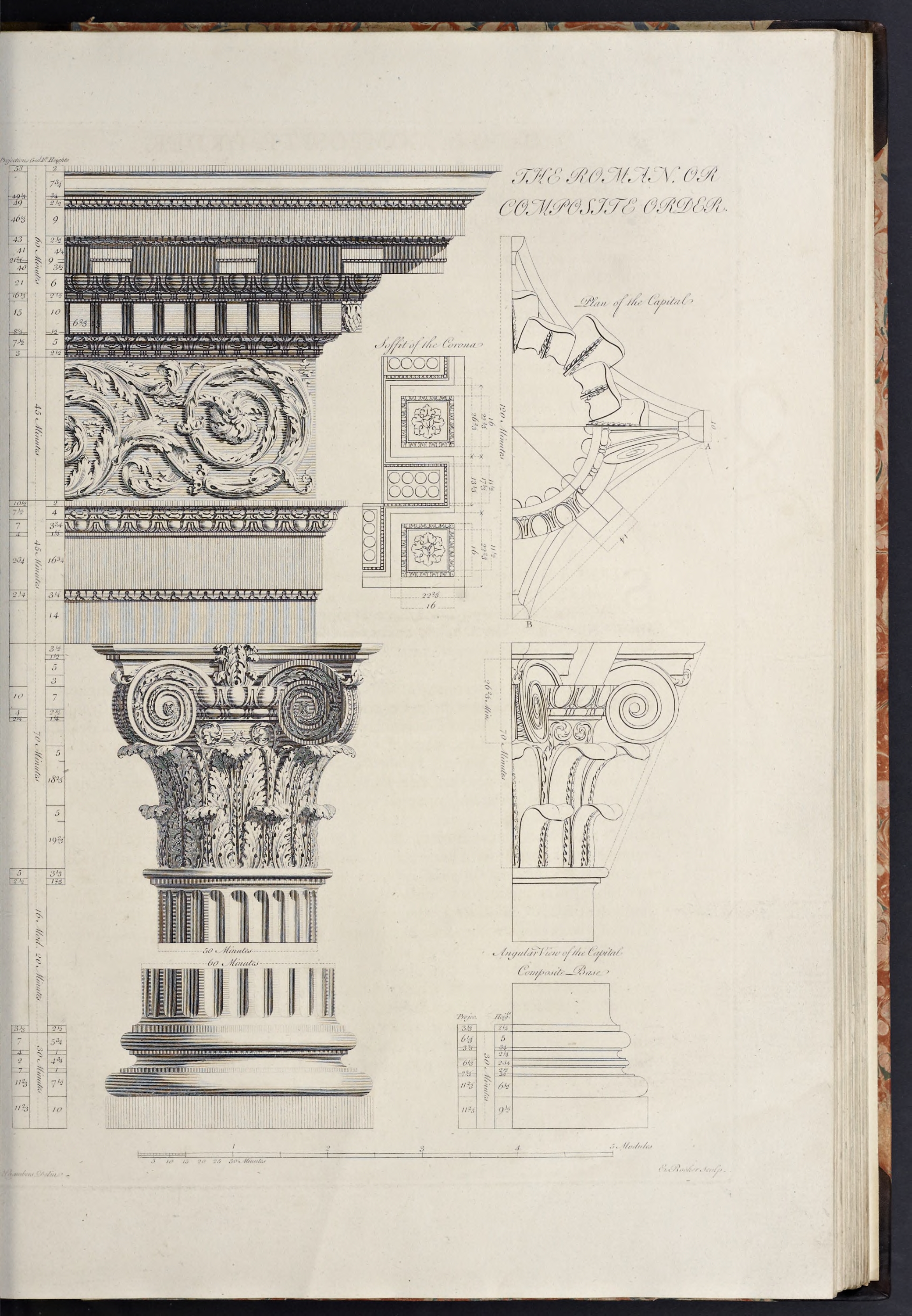
Chambers remarks “the projection of the Volutes is determined by a line drawn from the extremity of the Astragal to the extremity of a horn of the Abacus”, but his elevation drawing shows it projecting out farther, and his plan drawing shows it even with the bottom projection of the Abacus. The location above is therefore based on the latter location, which is also where James Gibbs has his Volute projection end.
Is Chambers is referring to the projection as seen from the front?
The projection of the leaves is set by Chambers as “the projection of the leaves is determined by another line drawn parallel to [the line setting the projection of the Volute] from the Fillet under the Astragal”.
Note: The next step is to create the profiles for the Acanthus leaves, for which Chambers provides heights
Chambers sets the projection
- Set Guides, going up from the bottom of the Capital, for 19
2/3 min and 182/3 min heights, then a pair of Guides 5 min below each of these Guides (this establishes the heights of the two rows of leaves, and the amount their tops drop downwards)Lower Leaf
Draw vertical line on 5 min and projection of astragal, and horizontal line at top out to diagonal projection line
Draw Arc from midpoint of vertical to midpoint of horizontal
Continue Arc outwards from endpoint to intersection of diagonal Guide and bottom of vertical
Continue Arc inwards to bottom of Campana
Upper Leaf
Set Guide at endpoint of Ovolo
Draw line from endpoint of ovolo to diagonal guide, divide in 2, erase outer half
Draw Arc from outer endpoint of line down to intersection of bottom Guide and diagonal Guide
Erase half line from above
Draw line on lower Guide of hang from projection of astragal to projection of ovolo, then draw line down from midpoint, and erase horizontal line
Continue Arc from above to top endpoint of line created above
Continue Arc down to bottom of campana
- Set Guides, starting from the top of the Capital and going up on the Blue Axis, for 45 min, 45 min, and 60 min (for the tops of the Architrave, Frieze, and Cornice)
- Draw a Rectangle, from the Guides marking the Centerline and top of the Cornice downwards to the Guides marking the bottom of the Architrave and the Upper Diameter
- Double-Click the Face just created and make it a Component
Entablature-Frieze-Core-profile - Set Guides, going up from the top of the Capital, for 14 min, 3
1/4 min, 163/4 min, 11/4 min, 33/4 min, and 4 min heights (for the Lower Fascia, Cyma Reversa, Upper Fascia, Fillet, and Ovolo, with the crowning Cavetto in the remaining space) - Set Guides, all going out from the Upper Diameter, for
1/2 min, 21/4 min, 23/4 min, 4 min, 7 min, 71/2 min, and 101/2 min projections (for the beginning & ending reveals of the Cyma Reversa, the Upper Fascia, the Fillet, the Ovolo, the beginning of the Cavetto, and the crowning Fillet) - Draw a Line, from the Guides marking the Upper Diameter and the height of the Lower Fascia, out to the next Guide, then diagonally upwards and outwards to the next Guide, then out to the next Guide (this forms the stand-in for the Cyma Reversa between the two Fascias)
- From the last Endpoint, continue the Line upwards to the next Guide, then out to the next Guide, then up to the next Guide (forming the Upper Fascia and Fillet over it)
- From the last Endpoint continue the Line diagonally upwards and outwards to the next Guide, then out to the next Guide, and once again upwards and outwards to the next Guide (forming the stand-in lines for the Ovolo & Cavetto)
- From the last Endpoint, continue the Line then up to the next Guide, then backwards to the Upper Diameter and then down to the Guide marking the height of the Lower Fascia (this forms the crowning Fillet of the Architrave)
- Double-Click the Face just created and make it a Component
Entablature-Architrave-Molding-profile - Replace the lowest diagonal line with a Cyma Reversa, the middle one with an Ovolo, and the topmost diagonal line with a Cavetto
- Erase the Guides below the top of the Architrave and to the right of the Upper Diameter
- Set Guides, going up from the Guide marking the bottom of the Cornice, for 2
1/2 min, 5 min, 101/2 min, 21/2 min, 6 min, 9 min, 21/2 min, 9 min, 21/2 min,3/4 min, and 73/4 min heights (for the combined Fillet & Astragal, the Cyma Reversa, Dentil Fascia, combined Fillet & Astragal, Ovolo, Modillion Fascia, Modillion Cymatium, Corona, Cyma Reversa, Fillet, and Cyma Recta, with the crowning Fillet in the remaining space) - Set Guides, going out from the Upper Diameter, for 3 min, 7
1/2 min, 81/3 min, 15 min, 161/3 min, 21 min, 212/3 min, 461/3 min, 462/3 min, 49 min, 491/3 min, and 58 min projections (for the combined Fillet & Astragal along with the start of the Cyma Reversa, the end of the Cyma Reversa, the Dentil Fascia, the projection of the corner Dentil, the combined Fillet & Astragal, Ovolo, Modillion Fascia, Corona, Cyma Reversa start and stop, Fillet, and Fillet over the Cyma Recta) - Draw a construction Line, between the Guides marking the bottom of the Cornice and the height of the combined Fillet & Astragal, Divide it into 3 parts, and set a Guide 1 part up from the bottom, then Erase the Divided Line (this will set the heights of the individual moldings; if you want a different division, place your Guide appropriately)
- Draw a construction Line, between the Guides marking the Upper Diameter and projection of the Astragal, and set a Guide at it’s Midpoint (for the projection of the Fillet)
- Using the Guides just set above, draw a Congé connecting the Frieze to the bottom of the Cornice
- From the top of the Congé, draw a Line up to the next Guide, then out to the next Guide
- Draw an Astragal, using the last Endpoint as the projection, leave the top right Line of the construction square for the final geometry, and from it’s Endpoint (even with the projection of the Astragal) draw a diagonal Line upwards and outwards to the next Guides (this forms the stand-in for the Cyma Reversa)
- Draw a Line, from the last Endpoint, out to the next Guide, then up to the next Guide (this forms the the Dentil Fascia)
- From the last Endpoint, draw a construction Line up to the next Guide, Divide it into 3 parts, and set a Guide at the top of the bottom part, then Erase the Line
- Using the dimensions I specify above, draw the Astragal between the Guides set above, with it’s top Midpoint (or the Endpoint of the finished Astragal) on the next Guide to the right
- Set a Guide
2/3 min back towards the Centerline from the Midpoint (bottom Endpoint) of the Astragal just drawn - From the bottom Endpoint of the Astragal, draw a Line inwards to the Guide just set, then down to the next Guide, then inwards to the Endpoint of the Line forming the Dentil Fascia
- From the top Endpoint of the Astragal, draw a diagonal Line upwards and outwards to the Guide Intersection, then out to the next Guide, then up to the next Guide (this forms the stand-in for the Ovolo, and the Modillion Fascia)
- From the last Endpoint, continue the Line up to the next Guide, then draw a Line out to the next Guide, then up to the next Guide (forming a stand-in for the Modillion Cymatium, and the Corona)
- From the last Endpoint, draw a Line out to the next Guide, then diagonally upwards and outwards to the next Guides, then out to the next Guide (forming the stand-in for the Cyma Reversa)
- Continue the Line up to the next Guide, then diagonally outwards and upwards to the next Guide Intersection, then up to the next Guide (forming the stand-in for the Cyma Recta)
- From the last Endpoint, draw a Line backwards to the Upper Diameter, then down to the bottom of the Conge under the Guide marking the bottom of the Cornice
- Double-Click the Face just created and make a Component (Entablature.Cornice.Molding.profile)
- Replace the lowest diagonal line with a Cyma Reversa, then next upwards with an Ovolo, the next two small ones with Cyma Reversa moldings, and the final large one with a Cyma Recta
- Delete all the Guides (some will be recreated, but this is easier)
- The Dentil can be created as a Rectangle 6
2/3 x 10 min with its upper left corner at the Intersection of the Dentil Band and Fillet over it, making it a Component profile (Entablature.Dentil.profile). - The Dentil projects an amount equal to it’s width, so Copy the Dentil Profile, Hide the original, Paste-in-Place, Right-Click, Make Unique, & Rename (removing the ‘profile’ from the name)
- Open the Component, and Push/Pull the Face out 6
2/3 min, then Close the Component - Set Guides at the bottoms of both the Corona and the Modillion Fascia
The Modillions are 9 min high (not counting their Cymatium), with the Upper Fascia being 4
1/4 min high, and the lower 31/2 min high, the intervening 11/4 min going to an Astragal. - Set a Guide 2
1/2 min down from the bottom of the Corona, then another 41/4 min below that, and a Guide 31/2 min up from the bottom of the Modillion Fascia (for the heights of the Cymatium, Upper Fascia, and Lower Fascia)The overall width of the Modillion & it’s Cymatium has to be that shown in the Soffit plan (which is 17
1/3 min) as that is bound to the distance between the elements (which is 222/3 min), and that is related to the spacing of the Dentils (which are 10 min on center). Therefore the distance between Modillions is 40 min on center.The width given on the Soffit for the Upper Fascia is 13
1/3 min wide, which is 4 min less than the width with the Cymatium, so that comes out correct. However, in the Soffit Plan, the width of the Lower Fascia is given as 111/2 min, which leaves the combined width of the two Astragals as 15/6 min. But the dimension scale indicates the difference between the Upper & Lower Fascia projections as being 1 min. As a result, I think the 111/2 min dimension is an error, and it should be 111/3 min instead, as this dimension matches the projection dimension on the scale, so that will be the dimension I use here. - Set Guides, to the right and from the Column Centerline, for 5
2/3 min, 62/3 min, and 82/3 min (for the half widths of the Lower Fascia, Astragal & Upper Fascia, and Cyma Reversa of the Cymatium)This still does not, however, indicate the dimension for the projection of the reveal of the Cyma Reversa of the Modillion Cymatium. As it is only 2 min wide (for a height of 2
1/2 min), it can’t be that big, but I think if you set it to1/3 min, that will work out good. That makes the reveal1/6 of the width of the total projection, and also makes the thickness between the bottom curves of the Cyma Reversa be 16 min, which equals the width of the corner panel of the Soffit (which may or may not mean anything, but I like the relationship). - Set a Guide
1/3 min to the right of that for the Upper Fascia (or 7 min from the Centerline) - Draw a Line, from the intersection of the Column Centerline and the bottom of the Modillion Fascia, out rightwards to the first Guide, then up to the Guide marking the bottom of the Corona, then continue it inwards to the Centerline, then down to the beginning
- Double-Click the Face just created, and Make Component (Entablature.Modillion.LowerFascia.Core.profile)
- Draw a Line, starting from the top-right corner of the Component just made, and go outwards to the Guide marking the projection of the Cyma Reversa
- From the last Endpoint, draw a Line diagonally inwards and downwards to the next Guides, then go inwards to the next Guide, then down to the next Guide
- Draw an Astragal, whose projection equals the Endpoint of the last Line, going down and in to the Lower Fascia Component, having it connect to the Upper Fascia with the top-right construction line
- From the bottom Endpoint of the Astragal, draw a Line going in to the Lower Fascia, then up to the top of that Component
- Double-Click the Face just created, and Make Component (Entablature.Modillion.UpperFascia.Molding.profile)
- Replace the diagonal line with a Cyma Reversa, and when you Paste the curve into the Component, Copy it and the two horizontal lines at top and bottom that it attaches to into memory, then Close & Hide the Component and Paste-in-Place
- Hide the Upper Fascia Molding Component, and draw a Line from the short horizontal Line pasted above, directly up on the Blue Axis to the longer Line above it, then Erase the part of that Line to the left of the new Face
- Double-Click the Face just created and Move it outwards on the Red Axis till it’s left edge is on the edge of the Cornice Profile marking the projection of the Modillion Fascia, then Cut/Copy it into memory, Open the Cornice Profile, Paste-in-Place, and Erase the Lines above it and to it’s left, separating it from the rest of the Cornice, then Close the Component
- Unhide the Upper Fascia Component & Erase all the Guides
- Copy the Upper & Lower Fascia Components into memory, Hide the originals, Paste-in-Place, Right-Click, Make Unique, and Rename (removing the ‘profile’ from the names)
- Open the Lower Fascia Core, and use Push/Pull to extend the Face out 18
1/3 min, then Select All, Move/Copy the Geometry from it’s top-right Endpoint to it’s top-left Endpoint, then Erase the lines in the middle to make it solid, Select the top outer three Edges, Copy them into memory, and Close the Component - Open the Upper Fascia Molding, join the Arc segments on the Cyma Reversa and the Astragal, then Paste-in-Place, and use Follow-Me to create the Molding, then Close the Component
- Select both the Lower Fascia Core & Upper Fascia Molding Components and Make a new Component (Entablature.Modillion)
- Unhide the Abacus Plan Component
- Select the Abacus Molding Profile Component, Copy it into memory, Hide the original, Paste-in-Place, Right-Click, Make Unique, and Rename (remove the ‘Molding.profile’ from the name)
- Move the Abacus profile frontwards so that it’s top-right corner is on the rear corner of the front right ‘horn’ (or protrusion) of the Capital Plan, with the profile still aligned along the Red Axis
- Open the Abacus Plan, Double-click the Face, then Deselect the Face itself (leaving only the Edges Selected), Copy them into memory, Close & Hide the Component, Open the Abacus profile, use Weld to join the Congé and line under it together, then Paste-in-Place, and use Follow-Me on the Face to create the Abacus form
- Draw a Line over the short straight inner Edges on the top & bottom of the nearest ‘horn’, then Erase the Edges showing on the flat Faces (the edges remaining from the inner Geometry), then turn on X-ray Style, and Erase the vertical lines remaining inside the ‘horns’ (the goal is to have Entity Info report a number for ‘Volume’ when you are done)
- Hide the Frieze & Cornice Components, Unhide the Cornice Molding Profile, and measure the distance from the Upper Diameter to the projection of the Dentil Fascia (which in this case is 8
1/3 min (which also means the distance from the Column Centerline to the Dentil Fascia is 331/3 min (the 25 min of the Upper Diameter plus the 81/3 min of the projection), then Move the Dentil Component into position based on these dimensionsNote: Exactly how much you move depends on how you are dealing with the Repeating Elements. In my case, with separate Dentils & Modillions, I moved my Dentil forward from the profile on the Green Axis for 33
1/3 min, then Unhid my Cornice Molding Component, and Moved it inwards on the Red Axis till it was centered on the Column Centerline. After this I Moved/Copied it, from the top-left corner out to the right for 10 min and repeated it 3 times, then did the same for the other side from the top-right corner, giving me 7 Dentils in a row (which cover the amount needed for a single side of a standalone Entablature). - Hide the Frieze & Cornice Components, Unhide the Cornice Molding Profile, and measure the distance from the Upper Diameter to the projection of the Modillion Fascia (which in this case is 21
2/3 min (which also means the distance from the Column Centerline to the Modillion Fascia is 462/3 min (the 25 min of the Upper Diameter plus the 212/3 min of the projection), then Move the Modillion Component into position based on these dimensionsNote: Again, this depends on how you are treating the Repeating Elements. For me, I moved my Modillion forwards on the Green Axis for 46
2/3 min, as it was already centered on the Column Centerline.In addition, I needed a copy on either side. As stated earlier in creating the profiles, the Modillions are spaced 40 min apart on center, so I Moved/Copied the Modillion Component 40 min on either side along the Red Axis (which is what is required for a single side of a standalone Entablature).
- With the Dentils and Modillions in place on one side of the standalone Entablature, you can either Select them all & Rotate/Copy them around the four sides of the Entablature, or make all of them into a Component (Entablature.RepeatingElements.standalone) and Rotate/Copy them around the Cornice (just like as was done for the Doric Repeating Elements)
- You can now Hide the Cornice Profile, and Unhide the Frieze & Cornice Components, and join the Frieze Core, Architrave & Cornice Molding, and Repeating Elements Components together into a single Component (Entablature.standalone)
- Open the Component, and Divide the Line into 3 parts, then Close the Component
- Using the Circle tool (with the number of Sides doubled from the usual 24 to 48 sides), and viewing the Plane so you can see it clearly (temporarily Hiding the Inner & Outer Profile Arcs may help), draw a Circle with a Center on the left or front Endpoint of the dividing line and with a Radius set to the end of the second part of that divided line going backwards, then draw another Circle but in reverse (so the Center is where the formers’ Radius was and the Radius is where the formers’ Center was)
- Now draw an Arc whose Center is the intersection of the two Circles created above, on the side farthest from a logical center-line running from the center of the Inner & Outer Profile curves, with the Radius being the Centers of the two Circles along the divided line in the middle of the Component (this arc will form the outer curve of the Bolster)
- Cut/Copy the Arc forming the outer curve, Double-Click the Circles just created and Erase them, Open the Left Profile Component, Paste-in-Place, and Close the Component
- Now we repeat the process above, but only using the one part of the divided line next to the Inner Profile, so draw a pair of Circles whose Centers are on the two Endpoints of this part, and then an Arc whose center is on the side closest to a logical center-line running from the center of the Inner & Outer Profile curves (the arc created between the two endpoints of the divided part will be the inner curve of the Bolster
- Cut/Copy the Arc forming the inner curve, Double-Click the Circles just created and Erase them, then Open the Left Profile Component, and Paste-in-Place
- Finally, Erase all the lines except for the two Arcs, use Weld to join the them together, and Close the Component
Note: For a shallower curve, copy the outer 3rd parts out on each side, Divide each part into 4 parts, and set the construction circles equal to one 3rd part plus 1 small part on each side, and make the arcs equal the original 2 parts and 1 part. By setting the arc centers farther away you can get a shallower curve while retaining the basic shape.
See ‘The Alternative C-Sc
The Column Shaft Profile
The Column Capital Profiles
The Composite Capital does not have any specific rules governing how it is designed, as there is no one look that is unique to it. However, the primary examples shown by Serlio & Vignola (and the only example shown by Palladio) is of the form that later become most associated with the term Composite, where a Doric-like necking is surrounded by two rows of Corinthian-like leafage, topped by an Ionic-style astragal & ovolo along with pairs of volutes at the four corners, topped by a Corinthian-like abacus. This is the form Chambers uses in his treatise and which will be illustrated below.
The Capital Abacus Plan
The Capital Abacus Profile
Note: The next step is the creation of the Abacus profile, which is problematic, as Chambers does not give any dimensions as to the projections of the Fascia, Fillet or Ovolo, except for the width of the column corner (and thus the projection of the Ovolo from the diagonal corner centerline), which is 10 min.
I tried searching for any references to the exact forming of the Abacus profile, and could not find any. I resorted to importing the drawing from Chambers’ Treatise, and after trial and error found that using the right profile of the elevation as a reference allowed the creation of a profile that would then match the center depiction as well.
The results are that the projection of the Ovolo from the Fillet is 3
To form the Fascia, I am using a Congé where the height is greater than the width (with a 5 to 6 proportion following James Gibbs).
As a result, please keep in mind that the above are my own dimensions, and not canonical, so if they appear wrong, they are my fault. Feel free to experiment and come up with your own proportions that suit your preferences.
Create a Congé With a Height Greater than it’s Width
The Congé can be drawn both as a true quarter-circle (which is what has been used before now), and as an arc where the height is greater than the width, by a varying degree.
This form was used by James Gibbs for his Column Cinctures, with a proportion of 6 parts high to 5 parts wide. Palladio shows two versions in his plates showing door and window moldings, one that is 3 parts high to 2 parts wide, and one 4 parts high to 3 parts wide.
Note: For this example here, I will follow Gibbs’ proportions.
Sources for constructing Leaves
Sebastien Le Clerc – A treatise of Architecture (plate 49, Fleuron, Caulicole, Acanthus & Laurel leaves, both elevation & profile)
Batty Langley – The Builder’s Jewel (Plate 40, Acanthus, Parsely, Olive & Laurel leaves, Elevation & profile, Caulicoli)
Brown, Bourne & Holst – Study of the Orders (Plate XV – Corinthian Large Leaf (elevation & profile), Rosette, Floweret, Caulicoli; Plate XVI – Corinthian Caulicoli & Volutes, Corinthian Small Leaf (elevation & profile), Stem; Fig 69 – Acanthus leaf of Tower of Winds)
Wooster Bard Field – Architectural Drawing (Plate 72 – Composite order profiles/sections; Plate 74 – Step-by-step display of leaves, Greek & Roman leaves)
Frank G. Jackson – Lessons on Decorative Design (plate XXX – Leaves)
James Page – Guide for drawing the Acanthus … (whole book)
The Entablature Profiles
There is no form that became common for the Composite Entablature. The form Serlio associated with it for his example was based on the uppermost tier of the Colosseum in Rome, with large modillions arising out of the Frieze, over a simple Architrave of three Fascias. That of Vignola is a composition almost opposite that of his Corinthian Entablature, with an Ovolo below the Dentils and a Cyma Reversa above them, as opposed to the Corinthian’s Cyma Reversa below the Dentils and the Ovolo above them, with an Architrave showing only two Fascias (derived from the Frontispiece of Nero according to Chambers). The design of Palladio is different again, with large double-height square Modillions under the Corona (reported by Chambers to be derived also from the Frontispiece of Nero), and an Architrave of two Fascias like Vignola. Scamozzi adopts the squared Modillions of Palladio, but makes them smaller, and placed above a sequence of Cyma Reversa, Fascia, & Ovolo, and goes back to the three-faced Architrave of Serlio.
The form shown by Chambers is an invention of my own, in which I have attempted to avoid the faults, and unite the perfections, of those above mentioned
(referring to Palladio, Vignola & Scamozzi). In form the Cornice is similar to Scamozzi’s, except instead of the plain Fascia he has inserted the Dentils from Vignola, while his Architrave is similar to those of Vignola & Palladio, with only two Fascias.
The Entablature Frieze Profile
The Architrave Profile
Chambers’ Composite Architrave is formed of two Fascias, separated by a Cyma Reversa, topped by a combination of a Fillet, Ovolo, Cavetto, and crowning Fillet.
The Cornice Profile
Chambers’ Composite Cornice is composed of a Fillet (connected to the Frieze with a Congé), under an Astragal and Cyma Reversa, which support the Dentil Fascia, above which is another Fillet & Astragal combination, under an Ovolo supporting the Modillions (which are formed as two Fascias separated by an Astragal) topped by a Cyma Reversa, over which is the Corona with it’s Cyma Reversa & Fillet, supporting the crowning Cyma Recta and Fillet.
As stated earlier, this is almost exactly like the Composite Cornice except for the Modillions themselves. Therefore, since you can insert the Composite Cornice Profile here, instead of recreating it (as the permanent, non-repeating, elements are the same), I am going to skip going over the steps again here.
See ‘The Cornice Profile’ on page … of ‘The Composite Order’ if you want to recreate the Component instead of copying and inserting it into this model.
Note: Twice in the Cornice Profile Chambers has a combination of Fillet and Astragal for which he only provides the combined heights and projection; in both I think the heights should be
Also, the dimension 46
Note: The last next Guide to the right marks the projection of the Dentils themselves, and after this is the second combination of Fillet & Astragal, for which Chambers provides only the combined heights (of 2
As the projection for the previous combination (from Upper Diameter to curve of Astragal) was 3 min, I can’t accept that the above projection is for a comparable width, in that it cannot be the combined projection from the Dentil Fascia to the curve of this Astragal. If you measure that distance in SketchUp it comes out to ~2
Therefore I believe it is actually meant to represent the projection of the Midpoint of the Astragal, which would also be where the Ovolo over it starts, which (if you gave the reveal under the Astragal the same size as the lower combination) would have the Fillet projecting
However, keep in mind that this is only my own extrapolation, and not canonical. So, if you would like a different projection, please feel free to do so and set your Guides and/or Geometry appropriately.
Tip: To do this I would draw my square starting at the next Guide, draw the Arc, Erase the square, then Move the Arc over to the correct position.
Note: The Modillion Cymatium runs above both the Modillions and the Modillion Fascia, so needs to be set here. As with the Doric Order, I will make the Cymatium run full length along the Fascia, as well as around the front & sides of the Modillion, and not worry about the Geometry hidden by the Modillion.
However, due to difficulties with the dimensions here, I am going to skip creating the Modillion Cymatium at this time, and will handle it below with the Cymatium, and then Move/Copy it here.
The Repeating Elements Of The Entablature
The repeating elements in the Composite Entablature are the Dentils and the Modillions, arranged so that Dentils are located directly under a Modillion, and with three whole Dentils between each Modillion (so the spacing from center to center of the Modillions equals the spacing of four Dentils (or three whole and two half Dentils) and four Interdentils, which is 40 min.
The Dentil Profile
The Dentils are 10 min high and 6
The Dentil Component
The Modillion Profile
Chambers’ Composite Modillions are rectangular blocks with two Fascias separated by an Astragal. These Modillions are similar to the Doric Mutule, and Chambers, in fact, shows them in his Soffit plan with 8 Guttae (or, at least, 8 circles, which I presume are Guttae, though no section or profile is shown).
Note: Due to the unusual nature of the inclusion of the Guttae in this Modillion, and the fact I have already given my method for constructing them when talking of the Doric Mutules, I am not going to add that feature here, but will leave the bottoms of the Modillions blank, like Palladio & Robert Chitham do.
The dimensions for the Modillions & their Cymatium have proven difficult for me to understand, as the various dimensions Chambers shows don’t add up for me. As a result the below contains some interpretation of the numbers, which are not canonical, just my own extrapolations from the data that I have at hand.
The Modillion Component
The Repeating Elements Component
Due to the existence of two repeating elements (the Modillion & Dentil) and the fact that they do not repeat the same, there are several ways you can create this component. You could just keep the two components separate, and array them down an Entablature separate. You could combine them together, with three full Dentils (and a half one at each end) centered under a Modillion. Or you could combine them together, and have four full Dentils under a Modillion, but off-center, with only the first Dentil directly centered under a Modillion and the remainder off to one side.
Personally I don’t feel the need for a Repeating Component in this case, and would just repeat each element individually. I choose this as no matter which of the above combinations you choose, you would still need to ‘pad’ the Entablature with extra Dentils at corners, and if you are not using an Order, arraying the elements individually allows for greater flexibility in varying the spacing if needed.
If you want to create a Repeating Elements Component, as was done for the Doric Order, it would just involve moving the Components Forward into proper position, joining them into a Component, and setting the proper Component Axes.
See ‘Assemble The Repeating Elements Component’ in ‘The Doric Order’ for a refresher on this type of component.
The Soffit of the Composite Entablature
The Soffit of this Order is similar to that of the Doric, in having panels inset into the plane, edged with moldings, featuring a central floral ornament. As the basics of this is already covered in the chapter The Doric Order, I will not go over it again here.
See The Soffit of the Doric Entablature on page … in The Doric Order for a refresher on forming this type of element.
For exact information and a visual example of the Soffit, look at the plate The Roman or Composite Order in Chambers’ Treatise.
Turning the Profiles into a Standalone Order
The Standalone Pedestal
The standalone Ionic Pedestal is created the same as for the Ionic Order, by using Push/Pull on the Pedestal Die Core (and using the rotated-edge technique here as well), and then using Follow-Me on the Base & Cap Moldings with the top & bottom Edges of the Die Core as the Path.
The Column Base Plinth
Creating the Base Plinth is the same as for all the other Orders.
The Cylindrical Components of the Column
Creating a plain, unfluted Composite Column Shaft, along with the Base Torii, and Capital Campana & Ovolo, can be done following the same steps as for the previous Orders, the only difference being the addition of the Campana Profile, which at this point is treated just like the other cylindrical elements.
See ‘Create the Wedges for a Cylindrical Component’ & ‘Form a Cylinder from Wedge Components’ in ‘The Tuscan Order’ on page … for a refresher.
If you want to apply fluting to this Order, it can be found under ‘Apply Ionic Style Fluting to a Column Shaft’ in ‘Enrichments to the Orders’.
Also, Chambers shows the Ovolo with Egg-and-Dart ornamentation, which can be found under ‘The Egg-and-Dart Enrichment of the Ovolo’ in the chapter ‘Enrichments to the Orders’.
The Abacus of the Column Capital
The Abacus of the Composite Column is the first that is not square, however, it can be dealt with in a similar manner to those of the Doric & Ionic Orders.
Tip: You should be able to Double-click the inner Face, then Deselect the Face itself, hit the Delete key, and only the Edges should be Erased, leaving the Face remaining.
Sebastien Le Clerc – A treatise of Architecture (plate 98 – Ionic angular order volutes)
Batty Langley – City & Country Builder’s & Workman’s Treasury (plate VII (Ionic Angle Volute)
The Volutes on the Front & Back of the Capital
The Composite Column (or at least this version of it) uses Ionic Volutes in it’s Capital, so that can be inserted now from the Ionic Order Model.
Note: To do this, Open the Ionic Order model file, combine the Capital Volute Eye & Fillet Components into a new Component (Composite.Volute) and ‘Save As’ into your Components directory. Then
The Ionic Volute is formed of the Fillet (whose front face diminishes in width as it goes deeper into the spiral of the Volute), the Hollow of the Volute (a channel stretching between the two Volutes on each side and penetrating into the spiral of each Volute between the curves of the Fillet), and the Eye of the Volute (a circle at the center of the Volute spiral).
The Capital Assembly
-
1. Unhide the Capital Bolster Belt Half, Ovolo & Column Shaft Components, Bolster Fillet, and the Group created from the Volute Components, and Explode the Group
2. Select the Bolster Belt Half, Bolster Fillet, & Bolster Half Components, along with the Volute Eye, Volute Fillet, & Volute Hollow Components, and make them a single Component (Column.Capital.quarter)
Note: At this point it might be convenient to open the various Components and Hide any Edges that you don’t want seen. 3. Move/Copy the Quarter Component out some distance on the Red Axis, Right-Click and choose Flip Along Component’s Red, then Move it back to the Midpoint of the Column so it meets up with the left side of the Hollow of the Volute Channel Component 4. Un-Hide the Abacus Core Component and set a pair of Guide diagonally from corner to corner to get it’s Center, then Select the two Quarter & Channel Components and Rotate/Copy them 180 degrees, using the intersection of the Guides set above as the Center 5. Erase the Guides, and Hide any Edges that shouldn’t be visible (notably where the Volute Channel’s join and where the Belt Halves join) 6. Un-Hide the Abacus Cymatium Component and Select both Abacus Components, the Ovolo Component, and all four Quarter Components, and make a Component (Column.Capital)
At this point you could assemble all the Column elements (Base Plinth & Torii, Shaft, and Capital) into a single Column Component if you want, as this would make it easy to then save as an external Component.
The Standalone Entablature
The basic form of this can be created just like that for the previous Orders, Copying the Profile Components & Making Unique, using Push/Pull to form the Frieze Core, then wrapping the Moldings around the Frieze Core with Follow-Me.
With the Standalone Entablature Moldings wrapped around the Core, only the Repeating Elements are let to be dealt with.
The Complete Standalone Order
Unhide the Column and standalone Pedestal & Entablature Components to see the finished result.
Composite Conclusion
Create the Profile for the Bolster S-Curve
This assumes a rectangular plane Component has been created, stretching between the Inner & Outer Profiles (showing the curves of the Belt & Bolster Fillet), and with a Line running through it directly connecting to the two curves