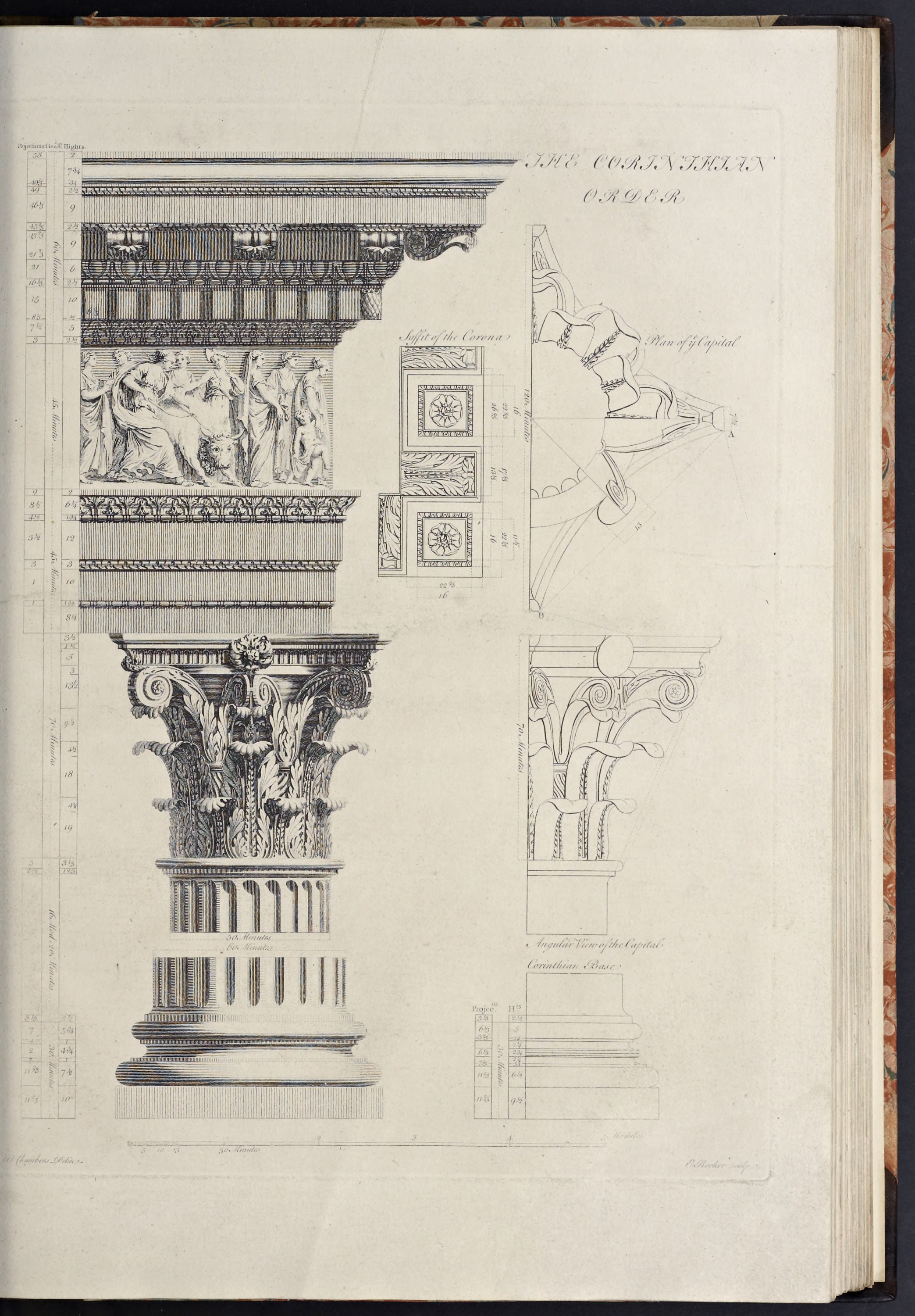
The Corinthian Order
The Corinthian order can be thought of as a product of three eras, with the capital being invented by the Greeks, the development of different bases and entablatures being the work of the Romans, and the codification of an actual order left to the Renaissance. Taller than the Ionic, it’s more elaborate capital, featuring foliage around a solid core, is matched by a more elaborate entablature, usually combining both the dentils of the Ionic entablature with elaborate scrolled modillions.
The basic characteristics of the Corinthian order are that:
- The column height ranges from 9 diameters high (per Serlio) to 10 diameters (per Vignola)
- The base is usually that established by Serlio after an example from the Pantheon in Rome
- The shaft, when fluted, is done in the Ionic style, though sometimes with added ornament in the lower third of the shaft’s flutes
- The capital is the order’s defining characteristic, with it’s plant leaves sprouting around a core that could be described as an urn or upside-down bell, with mini-volutes that meet at the four corners and the centers of the four sides
- The entablature was not specified by Vitruvius, so has no standard, but the most common type has an architrave of multiple fascias, and a cornice featuring a combination of both dentils and scrolled modillions, all elements more richly detailed than in previous orders
The Corinthian Order of Sir William Chambers
Chambers’ Corinthian order derives from that of Vignola, as that is uncommonly beautiful, and without dispute, superior to that of any other master: he, having artfully collected all the perfections of his originals, and formed a whole, far preferable to either of them
.
- The column height is 600 min, and the entablature height is 150 min, thus making the order 750 min high.
- The capital is 70 min high and the base is 30 min high, thus making the shaft 500 min high.
- The pedestal is 180 min high, thus making the order with the pedestal 930 min high.
- and, as with all Chambers’ orders, the lower diameter is 60 minutes, and the upper diameter is 50 minutes, making the diminution one-sixth of the column diameter.
Create the Order Profiles
- Start in parallel projection, front view
- Set a guide 30 min to the right of the Centerline (for the lower diameter), and another 11
2/3 min to the right of that (for the projection of the plinth & pedestal die)
The Pedestal Profiles
As with the previous pedestals, the Corinthian follows the same basic pattern, but just a little more elaborate than it’s predecssor.
- Set a guide 180 min up on the Blue Axis from the Baseline (for the height of the pedestal)
- Set guides horizontally and vertically on the Origin point
- Draw a rectangle from the guides marking the Centerline and top of the pedestal down and out to the guides marking the bottom of the pedestal and projection of the die
- Double-click the face just created, right-click, make component
Pedestal-Die-profile - Set guides, going up from the bottom of the die, for 26
2/3 min, 4 min, 1 min, 4 min, 1 min, and 31/3 min (for the plinth, torus, fillet, cyma recta, fillet, and cyma reversa) - Set guides, all going out from the die, for 13
1/3 min, 101/3 min, 5 min, 41/3 min, and2/3 min projections (for the plinth & torus above it, the fillet under the cyma recta, the fillet over the cyma recta, and the bottom & top curves of the cyma reversa) - Draw a line, from the bottom right of the die, out to the guide marking the projection of the plinth, and then up to the next guide marking the top of the plinth.
- Continue the line, inwards towards the Centerline, for 2 min (half the height of the torus), then draw a torus, using the endpoint of the line as the start point for the bottom of the torus, using the guide above it as the height
- Draw a line from the top endpoint of the torus inwards to the next guide, then up to the next guide
- Draw a diagonal line upwards and inwards to the next guide (as a stand-in for the upside-down cyma recta), then another line up to the next guide
- Draw a line, from the last endpoint, inwards to the next guide, then diagonally upwards and inwards to the next guide (as a stand-in for the upside-down cyma reversa)
- Draw a line inwards to the next guide, then down to the bottom of the pedestal
- Double-click the face just created and make it a component
Pedestal-Base-Molding-profile - Replace the lower stand-in diagonal line with an upside-down cyma recta, and the upper one with an upside-down cyma reversa
- Delete the guides to the right of the die and below the top of the pedestal
- Set guides, coming down on the Blue Axis from the top of the pedestal die, for 1
2/3 min, 31/3 min, 6 min, 41/3 min, 1 min, and 32/3 min heights (for the crowning fillet, cyma reversa, corona, ovolo, fillet, and cyma reversa) - Set guides, going out on the Red Axis and set from the projection of the pedestal die, for
2/3 min, 31/3 min, 4 min, 8 min, 131/3 min, 14 min, 17 min, and 172/3 min projections (for the beginning & ending of the cyma reversa curve, fillet, ovolo, corona, cyma reversa beginning & ending curves, and crowning fillet) - Draw a line, from the top-right corner of the pedestal, out to the guide marking the greatest projection of the pedestal cap, then down to the next guide, and then in to the next guide (forming the crowning fillet for the cap)
- Draw a diagonal line from the last endpoint downwards and inwards to the next intersecting guides (forming a stand-in for the cyma reversa)
- Draw a line, from the last endpoint, in to the next guide, then down to the next guide, then in to the next guide (forming the corona of the cap)
- Draw a diagonal line from the last endpoint downwards and inwards to the next guide (forming a stand-in for the ovolo)
- Draw a line from the last endpoint, down to the next guide, then in to the next guide, then another diagonal line downwards and inwards to the next guide (forming a stand-in for the cyma reversa)
- Draw a line from the last endpoint inwards to the next guide, then up to the top of the pedestal
- Double-click the face just created and make it a component
Pedestal-Cap-Molding-profile - Replace the top and bottom diagonal lines with cyma reversa moldings, and the middle diagonal line with an ovolo
- Erase the guides to the right of the die and below the top of the pedestal
The Pedestal Die Profile
The Pedestal Base Profile
The Corinthian pedestal is formed of a plinth at the bottom, topped by a torus under a fillet supporting an upside-down cyma recta, which supports another fillet on which sits an upside-down cyma reversa
The Pedestal Cap Profile
The Composite pedestal cap is formed of a cyma reversa molding topping the die, with a fillet separating it from an ovolo under the corona, which is topped by another cyma reversa with a crowning fillet.
The Column Base Profiles
Just as with the previous orders except the Tuscan, Chambers here uses the Attic base for his exemplar, but as with the Doric he offers an alternate base, which will be used here.
The Corinthian base shown by Chambers is derived from Serlio & Vignola, featuring a pair of torii over a Plinth, similar to the Attic base, but instead of a single scotia, here there are a pair of scotias, each flanked above and below by fillets, and separated by a pair of astragals.
- Set guides, going up from the Baseline, for 9
1/2 min, 61/2 min,3/4 min, 21/2 min, 23/4 min, 21/4 min,3/4 min, and 5 min heights (for the heights of the plinth, lower torus, lowest fillet, lower scotia, combined fillets & astragals, upper scotia, highest fillet and upper torus) - Set guides 3
2/3 , 61/3 , and 72/3 min to the right of the lower diameter (for the projections of the fillet under the upper torus, upper torus & dual astragals, and lowest fillet, the lower torus & plinth using the existing pedestal die guide) - Draw a rectangle the height and projection of the plinth
- Double-click the face just created and make component
Column-Base-Plinth-profile - Draw a torus above the plinth, going up to the first guide
- Draw a line from the last endpoint inwards to the first guide, then up to the next guide
- Draw a line from the last endpoint inwards to the guide marking the Lower Diameter, then continue it up to the next guide, then out to the second guide (i.e. for the projection of the upper torus and the astragals)
- Continue the line just drawn straight up to the next guide, then divide this line into 6 parts, and set guides coming down 1 part from top and going up 1 part from the bottom, and then one in the midpoint of the entire line, then delete the temporary divided line (though not the larger line below it)
- Draw a pair of astragals on either side of the midpoint guide set above, their height set by the guides above & below, with their projection being equal to the upper torus (or endpoint of the line just below the astragals), using construction squares (and leave the construction squares intact for the next step)
- Divide the rear half of the bottom of the lower astragal construction square into 3 parts, and set a guide backwards 1 part from the astragal midpoint (for the projection of the two fillets flanking the astragals)
- Draw a line, from the intersection of the line below the astragals and the guide just set, upwards to the bottom of the lower astragal
- Draw another line, directly upwards from that line on the same guide, from the top of the upper astragal up to the guide above it
- Erase the parts of the construction squares no longer needed (i.e. all except the short lines connecting the arcs to the lines coming off their top and bottom), along with the short line extending outwards from the fillet below the astragals, as well as the guide set for the astragal fillets
- From the endpoint of the line coming up off the upper astragal, draw a line inwards to the lower diameter, then up to the next guide, then out to the guide marking the projection of the fillet under the upper torus, then continue the line up to the next guide (forming the space for the upper scotia and fillet over it)
- Draw the upper torus, and connect the bottom of the torus to the line below it marking the end of the fillet under the torus
- Draw a line from the top of the upper torus, inwards to the centerline, then continue it downwards to the bottom of the lower torus, then outwards to the lower torus
- Double-click the face just created and make it a component
Column-Base-Torii-profile - Replace the two indentations with two scotia moldings
- Erase any guides below the top of the base, and to the right of the lower diameter
The Column Base Plinth Profile
The Column Base Torii Profile
The Column Shaft Profile
The Corinthian column shaft follows the design of the Ionic shaft, just with changes in proportions, other than height the most important perhaps being the return to a 5 min projection for the astragal at the top of the column.
- Set a guide 500 min up from the top of the base (for the height of the shaft)
- Set a guide 2
1/2 min up from the bottom of the shaft (for the lower cincture), and another 31/3 min up from that (for the height of the congé) - Set a guide 3
1/3 min out from the lower diameter (for the lower cincture) - Draw a line, from the top-left corner of the base, out to the guide marking the lower cincture projection, then continue it up to the next guide
- Draw a congé, from the last endpoint, up and in to the guide marking the lower diameter (thus completing the lower cincture of the column)
- Erase the guides to the right of the lower diameter and below the congé just drawn
- Now go back and draw a line, from the top-left corner of the base, up to the guide marking the top of the shaft (forming the column centerline)
- Set guides 3
1/3 and 12/3 min down from the top of the shaft (for the astragal and upper cincture), then another 21/2 min further down (for the height of the congé) - Set a guide 25 min out from the centerline (for the upper diameter)
- Set a guide 2
1/2 min out from the upper diameter (for the upper cincture; the astragal projects to the lower diameter) - Draw a Line from the last endpoint (at the top of the shaft Centerline) outwards to the guide marking the projection of the astragal, then use the endpoint of that line as the start for drawing the astragal, which you will draw going down to the next guide
- Draw a line from the endpoint of the astragal in to the next guide, then down to the next guide
- Draw a congé, from the last endpoint, down and in to the guide marking the upper diameter (thus completing the upper cincture)
- Erase the guides marking the height and projection of the upper cincture & astragal (leaving the guides marking the upper & lower diameters and top of the column shaft)
- Connect the top and bottom congé endpoints by applying entasis to the curve between the two points.
- Double-click the face just created and make it a component
Column-Shaft-profile - Erase any guides to the right of the upper diameter, and below the top of the shaft
The Column Capital Profiles
With the Corinthian capital the level of complexity increases, as does the level of interpretation, as there are very few drawings detailing how to form the individual elements of the Capital, and the descriptions vary according to the different authorities. What follows therefore, is going to involve a lot of interpretation, so please take the following as rough guides, that, once created, can then be adjusted to form your own interpretation following the Authority of your choice.
The form of Chambers Capital is fairly typical, with the Campana being as high as the Lower Diameter, with the Abacus adding a sixth of a Diameter to the overall height.
The Abacus plan features four horns coming out the corners and terminating in 45 degree angles (a form shared with the Angular Ionic and Composite capitals), with the profile featuring an Ovolo over a Fillet, connected to a Fascia with a Congé.
Chambers does not give a profile for the Campana form itself, so some interpretation is called for here, based on information gathered from other sources. The upper diameter of the Campana is shown on his plan to be equal to the width between the concave sides of the Abacus, and is formed as a beak molding, sometimes called the Lip of the Bell. According to Palladio, the diameter of the bottom of the Campana should be the same as the depth of the flutes of the Columns (which allows the lowest tier of leaves to kind of belly out at the bottom but still not be greater than the Upper Diameter of the Column).
Le Clerc has a profile of the Campana in his Treatise, which shows the bottom third curving downwards slowly into the projection of the Upper Diameter until about two-thirds of it’s way down, then sharply curving in to a greater depth. Above the bottom third of the Campana, the profile slowly curves out, increasing in curvature as it reaches the top. This is the basic form I will use below.
- Set a Guide 70 min up from the top of the Shaft (for the height of the Capital)
- Set a construction Guide 100 min above the highest Guide
- Draw a Line, from the intersection of the Column Centerline and the 100 min Guide, going out on the Red Axis, for 60 min
- Using the starting intersection above as the rotation point, Rotate the line just drawn 45 degrees clockwise, then set Guides at its Endpoint below and to the right (forming a square through which the line bisects diagonally), then Rotate/Copy the two Guides 180 degrees (forming the square in which the Abacus plan will be drawn)
- At the bottom Endpoint of the diagonal line, draw a Line, at right angles (or perpendicular) to the diagonal line), for 3
1/4 min on either side (forming the width of the top of the crowning Ovolo at the corners), then Select all three lines, and Rotate/Copy 90 degrees (centered on the upper Endpoint of the line), then repeat 3 times, Select all the lines and make them a Group - Using the top Endpoint of the upper short line at the bottom right corner as a center, draw a Circle (made with 48 sides) whose radius is equal to the bottom Endpoint of the lower short line at the top right corner, then reverse the process (so the new center is the previous radius and the new radius is the previous center), then draw an Arc, centered at the intersection of the circles away from the Centerline, stretching from the two points used above
- Cut/Copy the Arc into memory, Erase the construction circles, Paste-in-Place, and Rotate/Copy 90 degrees around the intersection of the diagonal lines 3 times
- Explode the Group, Erase the long lines crossing in the center, redraw a Line over an existing corner (to create a Face), then Select all the connected Geometry, and Make Component
Column-Capital-Abacus-plan - Set Guides, coming down from the Guide marking the top of the Capital, for 3
1/2 min, 11/2 min, and 5 min heights (for the Ovolo, Fillet, & Fascia of the Abacus) - Using the first Guide to the right of the Upper Diamater as the origin, set a Guide
3/4 min to the right of that, then a Guide 3 min beyond that, and another 31/3 min beyond that (for a filler space, and the projections of the Campana? what else goes here? a total width of 5 min, which is half the width of the corners of the Abacus plan) - At the intersection of the topmost Guide for the actual Capital (the one 70 min above the Shaft) and the first Guide to the right of the Upper Diameter, draw a Line out to the right to the last of the three Guides created above, then continue it diagonally downwards and inwards to the Guide intersection, then down to the next Guide (forming a stand-in for the Ovolo, and the Fillet below it)
- From the last Endpoint, draw a Congé going down and inwards to the next Guide, following the form used by James Gibbs
- From the bottom of the last vertical line drawn, draw a Line inwards to the next Guide, then up to the Endpoint of the line above it
- Double-Click the Face just created, Make Component
Column-Capital-Abacus-Molding-profile - Replace the diagonal line with an Ovolo, and Erase the three Guides created for this Component, along with all the vertical Guides except for the Column Centerline & Upper Diameter
- Set Guides, coming down from the bottom of the Abacus Molding profile, for 13
1/2 min, 91/2 min, 18 min, and 19 min (to set the heights of the three tiers of leaves) - Set a Guide 2
1/2 min back towards the Centerline from the Upper Diameter (as an approximation of the depth of the fluting, to determine the start of the curve of the bottom of the Campana) - Set a diagonal Guide, with a center on the intersection of the Upper Diameter and first Guide up from the bottom of the Capital, going 2 degrees clockwise from the Blue Axis
- Set another diagonal Guide, centered where the above Guide intersects the next Guide up from the bottom of the Capital (the 2nd Guide), this time going 3 degrees clockwise from the Blue Axis
- Draw a construction rectangle, starting at the bottom of the Capital and Upper Diameter, and going backwards and upwards to the Guide marking the depth of the fluting, making it twice as high as it is wide
- Where the first diagonal Guide intersects the top of the rectangle created above, draw a Line, along the diagonal Guide, upwards to the second Guide
- Erase the construction rectangle, and draw an Arc, coming down from the bottom Endpoint of the Line just drawn, and ending at the intersection of the top of the Shaft and the Guide marking the depth of the fluting, and making it tangent to the diagonal line
- Set another Guide, this time 4
1/2 min up from the third Guide above the top of the Shaft (this would also be 12 min below the bottom of the Abacus) - From the top of the Diagonal Line, draw another diagonal Line, this time along the second, 3 degree, diagonal Guide, upwards to the Guide just set above
- From the last Endpoint, draw an Arc, up to the next Guides upwards and outwards, making it tangent to the Line under it
- Draw an upside-down Ovolo, going up and back from the top Endpoint of the Arc just drawn, making it a quarter-circle
- Draw a Line, from the top of the Ovolo, inwards to the Centerline, then down to the bottom of the Capital, then out to the Endpoint of the Arc drawn in the double-square
- Double-click the Face just created, and Make Component
Column-Capital-Campana-profile - Erase the diagonal Guides, and that marking the depth of the flutes
- Select the Abacus Plan Component, and Rotate it 90 degrees on it’s center, so it is on the Red-Green Axis, then Move it down on the Blue Axis till it is at the Guide marking the top of the Capital, then Hide it (so it does not interfere with drawing the Profiles)
- Erase all the Guides except those for the Upper Diameter and the top of the Capital
The Capital Abacus Plan
The Capital Abacus Profile
The Capital Campana Profile
The Entablature Profiles
The Corinthian Entablature of Chambers is of a fairly standard type shown also by Vignola, Palladio, & Gibbs, and Chambers even remarks it differs little from that of Vignola
. It has two prominent elements repeated down its length, and these are the Dentils and Modillions of the Cornice, the latter of which are in the form of scrolled brackets.
- Set Guides, starting from the top of the Capital and going up on the Blue Axis, for 45 min, 45 min, and 60 min (for the tops of the Architrave, Frieze, and Cornice)
- Draw a Rectangle, from the Guides marking the Centerline and top of the Cornice downwards to the Guides marking the bottom of the Architrave and the Upper Diameter
- Double-Click the Face just created and make it a Component
Entablature-Frieze-Core-profile - Set Guides, going up from the top of the Capital, for 8
1/4 min, 13/4 min, 10 min, 3 min, 12 min, 13/4 min, and 61/4 min heights (for the Lower Fascia, Astragal, Middle Fascia, Cyma Reversa, Upper Fascia, Astragal, and Cyma Reversa, the Fillet occupying the remaining space) - Set Guides, all going out from the Upper Diameter, for 1 min, 1
1/2 min, 3 min, 31/2 min, 41/2 min, 81/2 min, and 9 min projections (for the Astragal & Middle Fascia, Cyma Reversa start and end, Upper Fascia, Astragal, Cyma Reversa ending, and Fillet) - Draw the lowest Astragal, using the lowest pair of Guides for it’s height, going back from the Guide marking its projection (leave the construction square for now)
- From the upper right corner of the construction square draw a Line up to the next Guide (for the Middle Fascia)
- From the last Endpoint, draw a Line out to the next Guide, then diagonally upwards and outwards to the Guide Intersection, then out to the next Guide, then upwards to the next Guide (this forms the stand-in for the lower Cyma Reversa, and the Middle Fascia)
- Draw an Astragal based on the heights and projection of the Guides above
- From the upper right corner of the square used to draw the Astragal draw a Line diagonally upwards and outwards to the next Guide, then out to the next Guide (for the Cyma Reversa)
- From the last Endpoint, draw a Line up to the next Guide, then out to the next Guide, and use the last Endpoint as the projection to draw an Astragal, going up and back, using the Guides set above (leaving just the horizontal parts of the construction square connecting the Arc to the Line under it and to the Guide marking its projection)
- From the Endpoint of the Line coming off the top of the Astragal draw a diagonal Line upwards and outwards to the Guide marking the projection of the upper Cyma Reversa, then out to the next Guide
- From the last Endpoint, draw a Line upwards to the next Guide, then inwards to the Upper Diameter, then down to the bottom of the construction square used to form the lowest Astragal
- Erase the remainder of the construction lines that are no longer needed for the lower Astragal (namely everything to the left of the Upper Diameter, the bottom right, and right side lines, and the small line to the left of the top of the Astragal)
- Double-Click the Face just created and make it a Component
Entablature-Architrave-Molding-profile - Replace the two diagonal lines with Cyma Reversa moldings
- Delete the Guides to the right of the Upper Diameter and below the top of the Architrave
- Set Guides, going up from the Guide marking the bottom of the Cornice, for 2
1/2 min, 5 min, 101/2 min, 21/2 min, 6 min, 9 min, 21/2 min, 9 min, 21/2 min,3/4 min, and 73/4 min heights (for the combined Fillet & Astragal, the Cyma Reversa, Dentil Fascia, combined Fillet & Astragal, Ovolo, Modillion Fascia, Modillion Cymatium, Corona, Cyma Reversa, Fillet, and Cyma Recta, with the crowning Fillet in the remaining space) - Set Guides, going out from the Upper Diameter, for 3 min, 7
1/2 min, 81/3 min, 15 min, 161/3 min, 21 min, 212/3 min, 461/3 min, 462/3 min, 49 min, 491/3 min, and 58 min projections (for the combined Fillet & Astragal along with the start of the Cyma Reversa, the end of the Cyma Reversa, the Dentil Fascia, the projection of the corner Dentil, the combined Fillet & Astragal, Ovolo, Modillion Fascia, Corona, Cyma Reversa start and stop, Fillet, and Fillet over the Cyma Recta) - Draw a construction Line, between the Guides marking the bottom of the Cornice and the height of the combined Fillet & Astragal, Divide it into 3 parts, and set a Guide 1 part up from the bottom, then Erase the Divided Line (this will set the heights of the individual moldings; if you want a different division, place your Guide appropriately)
- Draw a construction Line, between the Guides marking the Upper Diameter and projection of the Astragal, and set a Guide at it’s Midpoint (for the projection of the Fillet)
- Using the Guides just set above, draw a Congé connecting the Frieze to the bottom of the Cornice
- From the top of the Congé, draw a Line up to the next Guide, then out to the next Guide
- Draw an Astragal, using the last Endpoint as the projection, leave the top right Line of the construction square for the final geometry, and from it’s Endpoint (even with the projection of the Astragal) draw a diagonal Line upwards and outwards to the next Guides (this forms the stand-in for the Cyma Reversa)
- Draw a Line, from the last Endpoint, out to the next Guide, then up to the next Guide (this forms the the Dentil Fascia)
- From the last Endpoint, draw a construction Line up to the next Guide, Divide it into 3 parts, and set a Guide at the top of the bottom part, then Erase the Line
- Using the dimensions I specify above, draw the Astragal between the Guides set above, with it’s top Midpoint (or the Endpoint of the finished Astragal) on the next Guide to the right
- Set a Guide
2/3 min back towards the Centerline from the Midpoint (bottom Endpoint) of the Astragal just drawn - From the bottom Endpoint of the Astragal, draw a Line inwards to the Guide just set, then down to the next Guide, then inwards to the Endpoint of the Line forming the Dentil Fascia
- From the top Endpoint of the Astragal, draw a diagonal Line upwards and outwards to the Guide Intersection, then out to the next Guide, then up to the next Guide (this forms the stand-in for the Ovolo, and the Modillion Fascia)
- From the last Endpoint, continue the Line up to the next Guide, then draw a Line out to the next Guide, then up to the next Guide (forming a stand-in for the Modillion Cymatium, and the Corona)
- From the last Endpoint, draw a Line out to the next Guide, then diagonally upwards and outwards to the next Guides, then out to the next Guide (forming the stand-in for the Cyma Reversa)
- Continue the Line up to the next Guide, then diagonally outwards and upwards to the next Guide Intersection, then up to the next Guide (forming the stand-in for the Cyma Recta)
- From the last Endpoint, draw a Line backwards to the Upper Diameter, then down to the bottom of the Conge under the Guide marking the bottom of the Cornice
- Double-Click the Face just created and make a Component
Entablature-Cornice-Molding-profile - Replace the lowest diagonal line with a Cyma Reversa, then next upwards with an Ovolo, the next two small ones with Cyma Reversa moldings, and the final large one with a Cyma Recta
- Delete all the Guides (some will be recreated, but this is easier)
The Entablature Frieze Profile
The Architrave Profile
Chambers’ Corinthian Architrave is formed of three Fascias, the lower two separated by an Astragal, and the upper two separated by a Cyma Reversa, the whole topped by an Astragal, Cyma Reversa, and crowning Fillet.
The Cornice Profile
Chambers’ Corinthian Cornice is composed of a Fillet (connected to the Frieze with a Congé), under an Astragal and Cyma Reversa, which support the Dentil Fascia, above which is another Fillet & Astragal combination, under an Ovolo supporting Modillions (in the form of scrolled brackets) and their Fascia, topped by a Cyma Reversa, over which is the Corona with it’s Cyma Reversa & Fillet, supporting the crowning Cyma Recta and Fillet.
The Corinthian Cornice Dentil
The repeating elements in the Corinthian Entablature are the Dentils and Modillions in the Cornice.
As the Dentils are so simple in form, I am going to go ahead and make both the profiles and 3D element here.
- This can be created as a Rectangle 6
2/3 x 10 min with its upper left corner at the Intersection of the Dentil Band and Fillet over it, making it a Component profileEntablature-Dentil-profile . - The Dentil projects an amount equal to its width, so Copy the Dentil Profile, Hide the original, Paste-in-Place, Right-Click, Make Unique, & Rename (removing the ‘profile’ from the name)
- Open the Component, and Push/Pull the Face out 6
2/3 min, then Close the Component
The Dentil Profile
The Dentils are 10 min high and 6
The Dentil Repeating Element
The Corinthian Modillion Profiles
As stated above, the repeating elements in the Corinthian Entablature are the Dentils and Modillions in the Cornice.
While both the profile and element of the Dentils were created above, due to the complexity of the Modillions, the profiles wil be created here, but the 3D shapes will be created later on below.
- Hide everything except for the Cornice Profile, and Erase any Guides
- Set Guides at the height of the bottom of the Modillion Cymatium, and the bottom of the Modillion Fascia
- Set a Guide 22 min out from the Modillion Fascia
- Open the Cornice Profile, Copy the Edge of the Modillion Band into memory, Close & Hide the Component, Paste-in-Place (this is the height of the largest volute)
- Divide the Line into 8 parts (to become the Vertical Scale for the Large Volute)
- Set Guides at bottom, middle & top of the 5th part up from the bottom (to establish the position of the Eye)
- Rotate/Copy the lower 7 parts of the Vertical Scale rightwards 90 degrees clockwise (this establishes the width of the biggest scroll and the Horizontal Scale for the Large Scroll)
- Set a Guide 4 parts out from the Modillion Band on the Horizontal Scale (this sets the center of the Eye (whose vertical center is midpoint of part 5)
- Draw a Circle for the Eye, centered at the intersection of the last Guide and that in the middle of the 5th vertical part, whose Radius is
1/2 a part - Draw a diagonal square inside the circle so its corners are located at the top, bottom, left and right of the Circle
- Draw another square inside the last one, with its corners set at the midpoints of the diagonal square's sides
- Draw another diagonal square, inside the last one, oriented to match the first square, again from midpoints of the last square's sides (so you end up with a diamond inside a square inside a diamond inside a circle)
- Select the Vertical & Horizontal Scales and the Eye Geometry and Make Component
Entablature-Modillion-LargeVolute-construction - With its Center on the bottom-right corner of the square, draw an Arc clockwise 90 degrees, whose Radius is to the bottom of the Scroll
- Create the 2nd Arc, centered on the bottom-left corner of the square, again with a Radius equal to the previous Arc’s Endpoint
- Continue creating the 3rd & 4th Arcs, centered on the top-left corner & top-right corner of the square respectively, their Radius again being their respective previous Arc’s Endpoint
- The next Arc will have its center on the Midpoint of the bottom right side of the diamond, and its Radius will be directly below its center on the Blue Axis, but at the height of the Endpoint of the last arc (though not actually connecting to it)
- The 6th, 7th, & 8th Arcs will have their centers at the bottom-left, top-left, & top-right sides of the diamond respective, the Radius being the previous arc’s Endpoint
- Draw Lines, on the Red Axis, connecting the 4th and 5th Arcs, and the Endpoint of the final Arc with the Guide to its left
- Trip-Click one of the Arcs to Select them all, and Make Component
Entablature-Modillion-LargeVolute-Arcs-Outer - To create the Inner Arcs, set a Guide 1
1/2 parts up from the bottom of the Vertical Scale - Now draw two Arcs, just like above, the 1st centered on the bottom-right corner of the square, with a radius equal to the Guide just created, and the 2nd centered on the bottom-left corner of the square, with a radius equal to the last arc
- From the Endpoint of the last arc, draw a short Line out on the Red Axis to terminate it at the joint of the 6th & 7th outer arcs
- Trip-Click one of the Arcs to Select them (and the short line) and Make Component
Entablature-Modillion-LargeVolute-Arcs-Inner - Set a Guide at the top of the 3rd part up from the bottom of the Vertical Scale, and draw a Circle, centered in the Eye, with a radius to the this Guide, Double-click the Face, and Make Component
Entablature-Modillion-LargeVolute-Eye - Erase the Guides between the top and bottom of the Large Vertical Scale, then set a Guide 4 parts down from the top (this establishes the height of the Small Volute)
- Draw a Line, starting at the intersection of the top of the Modillion and its projection, down on the Blue Axis to the Guide just set above, and Divide it into 8 parts (this establishes the Small Vertical Scale)
- Rotate/Copy the upper 7 parts of the Vertical Scale leftwards clockwise 90 degrees from the top (this establishes the width of the smaller scroll and the Small Horizontal Scale)
- Set a Guide 4 parts inwards to the left on the Horizontal Scale, and another 4
1/2 parts down from the top on the Vertical Scale (this establishes the center of the Eye of the Small Volute) - Set Guides a half part above and below the horizontal Guide
- Create the same type of Circle, Diamond, Square, Diamond as for the Large Volute, centered on the Guides above, and using the last Guides as the radius
- Select the Small Scales and Small Eye, and Make Component
Entablature-Modillion-SmallVolute-construction - Now, repeat the creation of the Small Volute, just like the Large Volute, with setting centers for Arcs on the Eye and their radius as the previous Arc
- The first Arc Center will be the top-left corner of the square, and the radius is to the top of the Modillion
- The 2nd Arc center is the top-right corner, the 3rd Arc center is the bottom-right corner, and the 4th Arc center is the bottom-left corner
- The 5th Arc center is the top-left of the diamond (with the radius again being equal to but not touching the previous Endpoint), with the last Arc center at the top-right of the diamond
- Set a Guide 1
1/2 parts up on the Small Vertical Scale, which should equal the bottom Endpoint of the last Arc - Draw short Lines, on the Red Axis, connecting the 4th & 5th Arcs, and the last Arc to the Guide just set and the Guide setting the vertical center of the Eye
- Triple-Click the Arcs to Select them all, and Make Component
Entablature-Modillion-SmallVolute-Arcs - Draw a Circle, centered in the Eye, with a Radius set to the bottom of the Volute Arcs & last Guide, then Double-click the Face, and Make Component
Entablature-Modillion-SmallVolute-Eye - Use the Bezier tool to draw the curves connecting the two Volutes
- Delete the horizontal Guides between the top and bottom of the Modillion, and the vertical Guides between the beginning and end of the Modillion
- Set a horizontal Guide at the height of the Endpoint of the Inner Arc of the Large Volute (which should be 1
1/2 large parts up from the bottom of the Modillion) and another at the height of the start of the second revolution of the Small Volute (which should be 2 small parts down from the top of the Modillion) - Set vertical Guides at the Endpoints of the Large and Small Volutes
- Set a pair of vertical Guides 6 and 7 min to the left of the Endpoint of the Small Volute (both starting from the same point), and a vertical Guide 6 min to the right of the Endpoint of the Large Volute
- Activate the Bezier Curve tool, and set the Startpoint at the Endpoint of the Small Volute and the Endpoint at the Endpoint of the Inner Arc of the Large Volute, with the 1st Control Point at the top of the Modillion and the 7 min Guide set above, and the 2nd Control Point at the same height as the Endpoint of the Bezier Curve but on the 6 min Guide to it’s right
- Using the Bezier tool again, set the Startpoint at a point directly under the first Startpoint but on the 2nd revolution of the Small Volute and the Endpoint at the Endpoint of the Outer Arc of the Large Volute, with the 1st Control Point 6 min to the left of the Startpoint, and the 2nd Control Point at the same height as the Endpoint but 6 min to the right of it
- Select the two Bezier curves, and Make Component
Entablature-Modillion-S-curves - Erase the Guides between the top and bottom of the Modillion, and to the left of the last Guide on the right (marking the projection of the Modillion)
- Set a Guide 13
1/3 min to the right of the greatest projection of the Modillion (the Modillion itself, not its Cymatium) - Draw a Line, on the Guide marking the bottom of the Modillion, between the greatest projection of the Modillion and the last Guide set above (this sets the horizontal Scale for the Bolster)
- Set a Guide at the Midpoint of this Line
- Divide this Line into 2 half parts, and then Divide the leftmost half part into 6 parts, then Divide the first and last of these parts into 4 small parts each
- Set Guides at the end of the 3rd and 4th small parts going outwards from the left Endpoint of the Line (for the Outer Fillet and the small Fillet next to it)
- Set Guides at the end of the 2nd and 3rd small parts going inwards from the right Endpoint of the half Line (for half the Belt and the small Fillet next to it)
- Draw a Line, along the vertical Guide 13
1/3 min away from the Modillion, from the top to the bottom of the Guides marking the small Volute (this sets the vertical Scale for the Bolster) - Divide this Line into 4 parts, then Divide the lowest of those parts into 4 small parts, and set Guides at the top of the 1st and 4th small parts (setting the reveal for the inner Fillet and the Fillet next to the Belt)
- Select the two Scales and Make Component
Entablature-Modillion-Bolster-scales - Draw a Line, from the intersection of the Guides marking the projection of the Modillion and the bottom of the Small Volute, out to the right to the next Guide, then up to the next Guide, then out to the next Guide (forming the profile for the outer Fillet and inner Fillet)
- Draw a diagonal Line, from the last Endpoint outwards and upwards to the Guides marking the 3rd small part inwards form the right and the next Guide up, then continue the Line out to the right to the next Guide
- Draw a quarter-circle Arc, whose center is even with the last Endpoint and on the Guide marking the Midpoint of the front of the Bolster, starting from the last Endpoint and going downwards and rightwards to the Midpoint Guide
- Triple-Click the Geometry just created, and Make Component
Entablature-Modillion-Bolster-profile-half - Replace the diagonal line with an s-curve (similar to that for the Ionic Bolsters or the Cyma Recta & Reversa), setting the contstruction circles at the Midpoint & Endpoints, with the Arcs bulging upwards (or inwards) for the left half and downwards (or outwards) for the right half
- Delete all the Guides
The Corinthian Scrolled Modillion is an S-shaped bracket, composed of two spirals (or mini-volutes), the larger at the rear against the Cornice, the smaller at the front away from the building, with a Cymatium over the whole length, and the underside decorated with an acanthus leaf.
The Modillions are 9 min high (not counting their Cymatium), 13
The Modillion Cymatium Profile was created above as part of the Modillion Fascia of the Cornice, and will be copied into place for the Modillions themselves.
The Modillion can be created several ways, though Chambers does not provide an illustration of any methods. The below, therefore, is a method I came up with and adapted to fit here.
The Modillion Side Profile
The Modillion Front Profile
As stated above, the Modillion is 13
Form the 3D Elements
Following the process used for the Ionic Order, the basic elements will be created from their profiles, with interludes devoted to the more complex tasks where needed.
The Standalone Pedestal
- Hide all the components except those for the pedestal profiles
- Copy the three pedestal components into memory, hide the originals, Paste-in-Place the copies, Right-click on the components, Make Unique, and rename
- Open the
Pedestal-Die-standalone , and turn it into a square component, then close the component - Now wrap the cap & base moldings around the die core
- Select all three pedestal components and make a standalone component
Pedestal-standalone
The standalone pedestal is formed by wrapping the molding components around the central core component.
The Pedestal Die
The Pedestal Cap & Base Moldings
The Pedestal
The Column Base Plinth
- Unhide the Base Plinth Profile Component, Copy it into memory, Hide the original, Paste-in-Place, Right-Click, Make Unique, and Rename
Column-Base-Plinth - Open the component, and Push/Pull the face forward, sideways and backwards an amount equal to it’s width (as it is a perfect square)
- Hide the Base Plinth Component
The Cylindrical Components of the Column
Creating a plain, unfluted Corinthian Column Shaft, along with the Base Torus & Capital Campana, can be done following the same steps as for the Ionic Column.
- Unhide the Profiles, Select all three, Copy into memory, Hide the originals, Paste-in-Place, and rename (I replace “profile” with “wedge”)
- Turn each of the copied components into a wedge-based cylinder by creating 24 wedges of 15 degrees each, which are then Rotated & Copied to form the cylinder
- Draw a Line, from the bottom-left of the Base on the Centerline, going down a short distance, then draw a Circle (with 72 segments) on its Endpoint equal to the Lower Diameter
- With the Protractor Tool set a pair of Guides centered on the Circle, each 7.5 degrees to the front and back of the Red Axis, then draw Lines over the Guides from the Center to beyond the Edge, then Erase all but the small Arc between the diagonal lines
- Rotate the three Column Components 7.5 degrees counter-clockwise on the Centerline, then Cut/Copy the Arc into memory
- Open each Component, use Weld to join separate Arcs, Paste-in-Place, and use Follow-Me on the Face, then Reverse Faces, Erase the copied Arc, and Close the Component
- Select the three Wedges, Rotate/Copy them 15 degrees clockwise 23 times
- Move/Copy one of each of the Wedges out to the right, Open each one, and Hide the two side Faces, then Close & Erase each Component
- Select all the Wedge Components of each type and make a single Component (named without the ‘Wedge’) and repeat for each type
The Abacus Cymatium
- With the Campana and Abacus Plan & Profile Components visible, Copy the Profile Component into memory, Hide the original, Paste-in-Place, Make Unique, Rename
Column-Capital-Abacus - Move/Copy the Plan downwards till it is even with the top of the Profile, then Hide the original, and Explode the moved copy, and Delete the Face (leaving just the Edges)
- Move the Profile to one of the corners of the Plan so the outside corner of the Molding is on the Edge of the Plan (as the Plan represents the greatest projection of the Abacus)
- Triple-Click one of the lines or arcs of the exploded Plan (so you have all the Edges Selected), then Cut/Copy into memory
- Open the Cymatium Profile Component, use Weld to heal any separate Arcs if necessary, then Paste-in-Place and activate the Follow-Me tool against the Molding Face
- Draw a Line over one of the straight diagonal Edges to create a Face on the bottom, then Double-Click the center Face and Delete, which should leave a single Face stretching from outside Edge to outside Edge, then repeat for the top of the Abacus
- Close the Component
The Corinthian Capital Foliage & Volutes
The Campana is decorated with three rows of leaves, 8 on the lower level, 8 on the middle level, and 20 on the upper level (16 of these being smaller than the rest and wrapped around the lower curves of the Volutes). Chambers insists on using the Olive leaf, stating as are all the antiques at Rome, … the acanthus being seldom employed, but in the Composite (or Roman)
. This was not universal, as he continues De Cordemoy, however, prefers the acanthus, and observes that the flexible sprigs, which accompany the leaves of that plant, may more naturally be supposed to form the contour of the volutes, than the stiff branches of a laurel, or an olive tree
.
Just as with the Composite, I am not going to go into detailed creations of the leaves, but will create a simpler form, as that type of sculptural construction is beyond the scope of this book.
Some sources to use:
- Sebastien Le Clerc – A treatise of Architecture (plate 68 – elevation, plate 69 – parsley & olive leaves in elevation, draft leaf in half elevation, volutes, caulicole stem, rose)
- Brown, Bourne & Holst – Study of the Orders (Plate XV – Corinthian Large Leaf (elevation & profile), Rosette, Floweret, Caulicoli; Plate XVI – Corinthian Caulicoli & Volutes, Corinthian Small Leaf (elevation & profile), Stem; Fig 69 – Acanthus leaf of Tower of Winds)
- Wooster Bard Field – Architectural Drawing (Plate 71 – Corinthian order profiles/sections; Plate 74 – Step-by-step display of leaves, Greek & Roman leaves)
- ‘Space Carving – Computerphile’ (https://www.youtube.com/watch?v=cGs90KF4oTc), talking about cutting out visible parts piece by piece from different views Use for Leaves?
The Column Capital Assembly
The Standalone Column
With both the square and cylindrical elements of the Column formed, along with the special capital elements, now you can combine them all into a single column component.
- Unhide the
Column-Base-Plinth ,Column-Base-Torus ,Column-Shaft ,Column-Capital , and join them together into a singleColumn-standalone - Hide the new component
The Standalone Entablature
The standalone Corinthian Entablature is initially created using the same technique as for the previous orders, with the Molding Components being wrapped around the Frieze Core. After that, the Dentil & Modillion Components need to be positioned.
Over the Centerline of each Column both a Dentil and Modillion is centered, and the Modillions are 40 min apart on center, with three full Dentils between them along with the two halves between the Modillion centerlines. As with the Ionic Entablature, the spacing of columns has to take this into account.
- Unhide the Entablature Profiles (Architrave, Frieze, & Cornice), Copy the Components, Hide the originals, Paste-in-Place, Make Unique, and Rename (as with the Pedestal, I change “profile#1” to “standalone”)
- Open the Frieze Core component, Push/Pull the Face forwards 25 min (Chambers’ standard dimension for the Upper Diameter), then repeat on the new left & back Faces
- Use the Follow-Me Tool to wrap the Moldings (Architrave aka Tenia & Cornice) around the Frieze Core
- Unhide the
Entablature-Dentil component - Copy/Move it forwards on the Green Axis till it’s front left corner is even with the dentil fascia (which should be 26
2/3 min), then hide the original - Now move/copy it backwards on the Green Axis 10 min and repeat 6 times (for a total of 7 dentils on each side of a standalone entablature)
- The Column & Pilaster Components (as these can be used ‘as is’ so to speak)
- The Pedestal & Entablature Core Profile Components (as these can be used to stretch or span between the Columns or Pilasters)
- The Pedestal & Entablature Molding Profile Components (as these can be used to wrap around standalone elements as well as existing structures, both with or without the Column & Pilaster Components)
- The Entablature Dentil Component (to be used either rotated around a standalone Entablature or arrayed down the length of a wall or building)
Once the Molding Components have been wrapped around the Core, and the Repeating Elements Rotated/Copied, Select all the Entablature Components and make them a Component
The Complete Standalone Order
Unhide the Column and standalone Pedestal & Entablature Components to see the finished result.
Corinthian Conclusion
The following is the suggested list of Components to save for this Order: