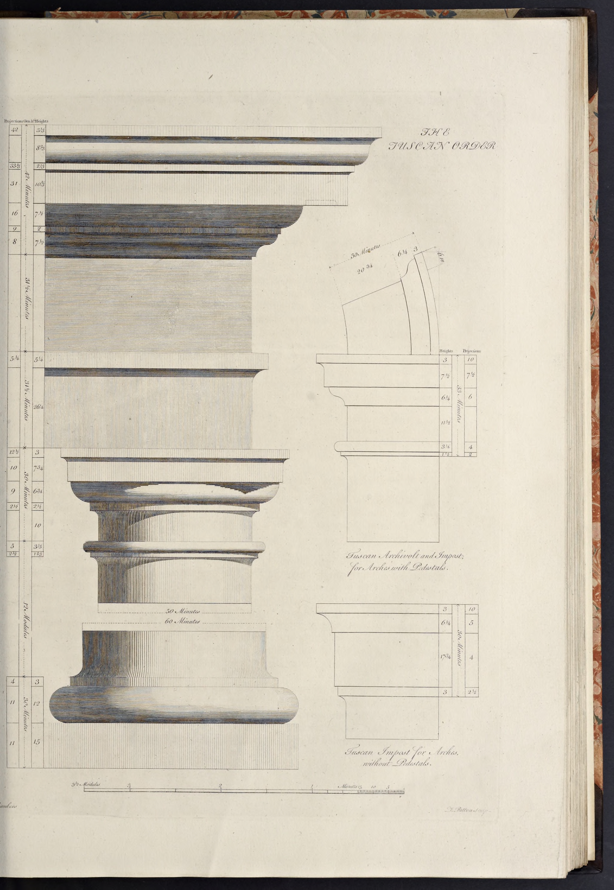
The Tuscan Order
The Tuscan order was invented by Renaissance theorists (primarily Sebastiano Serlio) from a brief description by Vitruvius of an Etruscan temple in Book IV of his treatise De Architectura. It is the shortest and sturdiest of the orders, and the plainest, generally with no decoration save the curves of its moldings.
The basic characteristics of the Tuscan order are that:
- The column height is almost always shorter than the Doric, ranging from 6 diameters high (per Serlio) to 7
1/2 diameters (per Scamozzi) - The base is almost always that derived from Vitruvius, formed of only a plinth & torus (though only Serlio followed Vitruvius in making the plinth round instead of square)
- The shaft is never fluted, though it is sometimes bound in rusticated quoins
- The capital is always plain, sometimes (as in Palladio’s example) even lacking a crowning cymatium to the abacus
- The entablature generally does not have any repeating elements, though Palladio shows a primitive form with joists over the frieze and Scamozzi shows primitive triglyphs in his frieze, in both cases repeating only over the columns
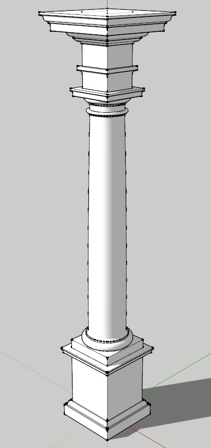
The Tuscan Order Of Sir William Chambers
Chambers’ Tuscan Order features a column derived from Vignola, along with a cornice from Scamozzi, with such alterations as were evidently necessary to render it perfect
.
- The column height is 420 min, and the entablature height is 105 min, thus making the order 525 min high.
- The capital is 30 min high and the base is 27 min high, thus making the shaft 363 min high.
- The pedestal is 126 min high, thus making the order with the pedestal 651 min high.
- and, as with all Chambers’ orders, the lower diameter is 60 minutes, and the upper diameter is 50 minutes, making the diminution one-sixth of the column diameter.
Create the Order Profiles
- Start in parallel projection, front view
- Set a guide 30 min to the right of the Centerline (for the lower diameter), and another 11 min to the right of that (for the projection of the plinth & pedestal die)
The Pedestal Profiles
The Tuscan pedestal of Chambers is very simple, with only a single cyma recta or reversa molding at top and bottom, other than fillets & congés. The height of the pedestal is divided into 9 parts, with 1 going to the cap at top and 2 going to the base at bottom, with the remainder forming the die in between.
The pedestal will be modeled as a solid core made of the die, running the whole height of the pedestal, with the moldings of the cap and base being wrapped around this core element. For information about why I do it this way and alternatives, see the section Modeling Optimization in the Appendix.
- Set a guide 126 min up from the Baseline (for the height of the pedestal)
- Set guides horizontally and vertically on the Origin point (forming the bottom of the pedestal and the axis of the order)
- Draw a rectangle, from the intersection of the top guide & Centerline, down and out to the intersection of the last guide on the right & Baseline
- Double-click the face just created, right-click, make component
Pedestal-Die-profile - Set guides going up from the bottom of the pedestal die, for 18
2/3 min, 21/6 min, 52/3 min, and 11/2 min (for the plinth, base fillet, cyma recta, and fillet) - Set guides, going out rightwards, and all set from the projection of the pedestal die, for 10 min, 8 min, and 2 min (for the plinth, fillet under the cyma recta, and fillet over the cyma recta & under the top congé)
- Draw a line, from the bottom-right corner of the pedestal die, out to the last guide, then up to the next guide, then in to the next guide, and up to the next guide (forming the plinth and fillet right above it)
- Draw a line diagonally upwards and inwards to the next intersecting guides, then up to the next guide (forming a stand-in line for the upside-down cyma recta, and the fillet above it)
- From the last endpoint, draw a congé going upwards and inwards connecting it to the die
- Draw a line, from the top of the congé, down to the bottom of the pedestal
- Double-click the face just created and make it a component
Pedestal-BaseMolding-profile - Replace the stand-in diagonal line with an upside down cyma recta
- Erase the guides to the right of the die, and below the top of the pedestal
- Set guides, comng down from the top of the die, for 2 min, 6 min, 1 min, and 5 min (for the crowning fillet, the corona, fillet, and cyma reversa)
- Set guides, going rightwards and all from the projection of the die, for 12 min, 10 min, 5
2/3 min, and 5 min (for the crowning fillet, corona, fillet, and top curve of the cyma reversa) - Set a guide
2/3 min out from the die (for the beginning reveal of the cyma reversa) - Draw a line, from the top right corner of the pedestal die, out to the last guide, then down to the next guide (forming the crowning fillet for the cap)
- Draw a congé, curving downwards and inwards to the next guide
- Draw a line, from the bottom of the congé, down to the next guide, then in to the next guide, then down to the next guide (forming the corona of the cap)
- Draw a line, from the last endpoint, inwards to the next guide, then diagonally downwards and inwards to the next guide, then in to the next guide (forming the stand-in for the cyma reversa and the fillets above & below it)
- Draw a line, from the last endpoint, up to the top of the pedestal
- Double-click the face just created and make it a component
Pedestal-CapMolding-profile - Replace the stand-in diagonal line with a cyma reversa
- Erase the guides to the right of the die and below the top of the pedestal
The Pedestal Die Profile
The Pedestal Base Profile
The Tuscan pedestal base is formed of a plinth at the bottom, topped by a fillet supporting an upside-down cyma recta, and crowned by a fillet that merges into the die with a congé.
The Pedestal Cap Profile
The Tuscan pedestal cap is formed of a cyma reversa molding above the die, topped by a fillet, over which is a corona, which is connected to the crowning fillet with a congé.
The Column Base Profiles
Chambers’ Tuscan base is of the standard type derived from Vitruvius, with only two elements, a square plinth and large cylindrical torus above it.
- Set guides, going up from the top of the pedestal for 15 min, and 12 min (for the heights of the plinth and torus)
- Draw a rectangle, from the intersection of the Centerline and height of the plinth downwards and outwards to the top of the pedestal and projection of the plinth
- Double-click the face just created and make it a component
Column-Base-Plinth-profile - Draw a torus above the plinth, going backwards towards the Centerline from the projection of the plinth
- Draw a line, from the endpoint of the top of the arc just created, back to the Centerline, then down to the top of the plinth, then out to the bottom of the arc
- Double-click the face and make it a component
Column-Base-Torus-profile - Erase the guides below the top of the base and to the right of the lower diameter
The Column Base Plinth Profile
The Column Base Torus Profile
The Column Shaft Profile
The Tuscan column shaft introduces what is the same basic profile for all the column shafts illustrated here, being comprised, as noted earlier, of the cincture at the bottom, a congé above it, the main body of the shaft (with entasis applied), and a cincture and astragal at the top.
- Set a guide 363 min up from the top of the base (for the height of the shaft)
- Set a guide 3 min up from the bottom of the shaft (for the lower cincture height)
- Set a guide 4 min out from the lower diameter (for the lower cincture and congé projection)
- Draw a line, from the top-left corner of the torus, out to the last guide, then up to the next guide (for the lower cincture)
- Draw a congé, from the last endpoint, up and in to the lower diameter (to connect the lower cincture to the shaft)
- Erase the guides to the right of the lower diameter and below the congé
- Now go back and draw a line, from the intersection of the top of the base and the Centerline, up to the guide marking the top of the shaft (to form the column centerline)
- Set guides 3
1/3 min and 12/3 min down from the top of the shaft (for the astragal and upper cincture heights) - Set a guide 25 min out from the Centerline (for the upper diameter)
- Set another guide 2
1/2 min out from the upper diameter (for the upper cincture projection; the astragal will project equal to the lower diameter. - Draw an astragal coming down from the top of the shaft and back from the lower diameter
- Draw a line from the top of the shaft centerline outwards to the top of the astragal
- From the bottom of the astragal draw a line inwards to the next guide, then down to the next guide (for the upper cincture)
- Draw a congé, from the last endpoint, down and in to the upper diameter (to connect the upper cincture to the shaft)
- Erase the guides marking the heights and projection of the upper cincture, leaving the guides for the upper & lower diameters
- Draw a temporary diagonal line connecting the endpoints of the two congé moldings (or connecting the start & stop points for applying entasis, as explained below)
- Double-click the face just created and make it a component
Column-Shaft-profile - Finish by applying entasis to the shaft profile
- Erase the guide marking the lower diameter
The Column Capital Profiles
The Tuscan capital of Chambers is formed with a simple necking (equal in width to the upper diameter), connecting with a congé to a fillet over it, which supports an ovolo, on which sits the square fascia of the abacus, connected by a congé to a simple crowning fillet.
- Set a guide 30 min up from the top of the shaft (for the height of the capital)
- Set guides, coming down from the guide just made, for 3 min and 7
3/4 min (for the fillet & fascia of the abacus) - Set guides, going out from the upper diameter, for 10 min, and 12
1/2 min (for the fascia & fillet of the abacus) - Draw a line, from the intersection of the Centerline and top of the capital, out to the last guide, then down to the next guide (forming the crowning fillet of the capital abacus)
- Draw a congé going inwards and downwards from the last endpoint to the fascia of the abacus
- Draw a line from the bottom endpoint of the congé down to the next guide, then inward to the Centerline, then up to the top of the capital (forming the fascia and fillet of the abacus)
- Double-click the face just created and make it a component
Column-Capital-Abacus-profile - Erase the guides to the right of the upper diameter
- Set guides, coming down from the bottom of the abacus, for 6
3/4 min, and 21/2 min (for the ovolo, and the fillet under it) - Set guides, going out from the upper diameter, for 2
1/2 min, and 9 min (for the fillet above the necking, and the ovolo) - Draw a line, from the bottom-left corner of the abacus, outwards to the last guide, then continue it diagonally downwards and inwards to the next guide, then down to the next guide (forming a stand-in for the ovolo, and the fillet under it)
- From the last endpoint, draw a congé going inwards and downwards to the upper diameter
- Draw a line from the bottom of the congé down to the top of the shaft, then inwards to the Centerline, then upwards to the bottom of the abacus (forming the necking of the capital)
- Double-click the face just created and make it a component
Column-Capital-Ovolo-profile - Draw an ovolo to replace the stand-in diagonal line
- Erase the guides to the right of that marking the upper diameter, and below the top of the capital
The Column Capital Abacus (Fascia)
The Column Capital Ovolo
The Entablature Profiles
The Tuscan entablature of Chambers is formed very simply, featuring a single fascia architrave with simple cymatium, plain frieze, and simply modeled cornice with no repeating elements. It also follows a common pattern of dividing the entablature into ten parts, giving three to the architrave, three to the frieze, and four to the cornice.
The entablature will be modeled as a solid frieze, running the whole height of the entablature, with the moldings of the architrave and cornice being wrapped around this core element. For information about why I do it this way and alternatives, see the section Modeling Optimization in the Appendix.
- Set guides, going upwards from the top of the capital, for 31
1/2 min, 311/2 min again, and 42 min heights (for the tops of the architrave, frieze, and cornice) - Draw a rectangle, from the guides marking the Centerline and top of the cornice downwards to the guides marking the top of the capital and the upper diameter
- Double-click the face just created and make it a component
Entablature-Frieze-profile - Set a guide, coming down from the top of the architrave, for 5
1/4 min (for the height of the architrave fillet) - Set a guide 5
1/4 min out from the upper diameter (for the projection of the fillet) - Draw a line, from the intersection of the frieze core and top of the architrave, out to the next guide, and then down to the next guide (forming the architrave fillet)
- Draw a congé going inwards and downwards from the last endpoint to the frieze core
- Draw a line from the bottom endpoint of the congé up to the top of the architrave (forming the architrave molding)
- Double-click the face just created and make it a component
Entablature-ArchitraveMolding-profile - Erase the guides to the right of the upper diameter and below the top of the architrave
- Set guides, going up from the bottom of the cornice, for 7
1/2 min, 2 min, 71/2 min, 102/3 , 21/3 min, and 82/3 min heights (for the cyma reversa, fillet, ovolo, corona, fillet, and cyma recta, with the crowning fillet occupying the remaining space) - Set guides, going out from the frieze core, for 1 min, 8 min, 9 min, 16 min, 31 min, 33
1/3 min, and 42 min projections (for the start of the cyma reversa, the end of the cyma reversa, the fillet, ovolo, corona, fillet, and cyma recta & fillet) - Draw a line, from the guide marking the bottom of the cornice and the frieze core, out to the next guide, then diagonally upwards and outwards to the guide intersection, then out to the next guide (forming the stand-in for the cyma reversa)
- From the last endpoint, draw a line upwards to the next guide, then diagonally upwards and outwards to the guide intersection (forming the fillet and stand-in for the ovolo)
- From the last endpoint, draw a line out to the next guide then up to the next guide (for the bottom and face of the corona up to the fillet over it)
- Draw a congé coming down and inwards from the fillet over the corona (in this instance the top and projection of the congé, or bottom and projection of the fillet, are represented by guides)
- Draw a line from the top of the congé up to the next guide, then diagonally upwards and outwards to the next guide intersection, then up to the next guide (for the fillet, stand-in for the cyma recta, and crowning fillet)
- Draw a line from the last endpoint inwards to the frieze core, then down to the guide marking the bottom of the cornice
- Double-click the face just created and make it a component
Entablature-CorniceMolding-profile - Replace the diagonal stand-in lines with, going up from the bottom, a cyma reversa, ovolo, and cyma recta
- Set a Guide 2 min up from the bottom of the corona
- Set a Guide 1 min to the right of the Guide marking the projection of the ovolo, and another Guide 3 min to the left of the Guide marking the projection of the corona
- Draw a congé, from the intersection of the first guide inward and the bottom of the corona, upwards and inwards to the top of the drip mold
- From the endpoint of the congé, draw a line inwards to the next guide, then down to the bottom of the corona
- Select the lines and arc just created, cut them into memory, open the
Entablature-CorniceMolding-profile , Paste-in-Place, erase the line at the bottom of the drip molding, then close the component - Erase all the guides, unhide all the components (if you hid any) and Zoom Extents
The Entablature Frieze Profile
The Entablature Architrave Profile
Chambers’ Tuscan architrave is formed as a single fascia, connected to a crowning fillet by a congé.
The Entablature Cornice Profile
Chambers’ Tuscan cornice comprises a cyma reversa over the frieze, topped by a fillet and ovolo, over which is the corona, connected by a congé to the fillet over it, which itself is topped by a cyma recta and crowning fillet.
The Entablature Soffit Profile
There is one part of the cornice that was not drawn, and that is the drip molding under the soffit, as Chambers depicts this as dashed lines without any dimensions.
Extrapolating from the diagram with a pair of calipers, I get a height of 2 min, and a position 1 min out from the projection of the ovolo under it, and 3 minutes back from the edge of the corona; in addition it has a congé connecting the front edge to its top surface.
Form the 3D Elements
Due to the simplicity of the Tuscan Order, the profiles can be used as is to construct the various 3D elements of the order, such as the pedestal, column and entablature.
The Standalone Pedestal
- Hide all the components except those for the pedestal profiles
- Copy the three pedestal components into memory, hide the originals, Paste-in-Place the copies, Right-click on the components, Make Unique, and rename
- Open the
Pedestal-Die-standalone , and turn it into a square component, then close the component - Now wrap the cap & base moldings around the die core
- Select all three pedestal components and make a standalone component
Pedestal-standalone
The standalone pedestal is formed by wrapping the molding components around the central core component.
The Pedestal Die
The Pedestal Cap & Base Moldings
The Pedestal
The Column Base Plinth
The column base plinth for all of Chambers orders is a plain square cube.
- Unhide the
Column-Base-Plinth-profile , copy it into memory, hide the original, Paste-in-Place, Right-click, Make Unique, and renameColumn-Base-Plinth - Open the component, and Push/Pull the face forward, sideways and backwards an amount equal to it’s width (as it is a perfect square)
- Once done, close and hide the component
The Cylindrical Components of the Column
Here we turn the profile components for the Column Base, Shaft & Capital into 3D wedges, which are then combined into standalone Base, Shaft & Capital components.
- Unhide the
Column-Base-Torus-profile ,Column-Shaft-profile , andColumn-Capital-Ovolo-profile , select all three, copy them into memory, hide the originals, Paste-in-Place, right-click, Make Unique, and rename - Turn each of the copied components into a wedge-based cylinder by creating 20 wedges of 18 degrees each, which are then rotated & copied to form the cylinder
- In Front view, select all the individual wedge components of each element and combine into single
Column-Base-Torus ,Column-Shaft &Column-Capital-Ovolo components as appropriate - Hide the three cylindrical components just created
The Column Capital Abacus
Chambers’ Tuscan abacus is very simple, with only a fillet and fascia, the fillet connecting to the fascia with a congé. As a result it has been treated as a single entity when creating the profile, and will therefore be treated as such below. As the abaci of the other orders are more complex, a different treatment will be introduced to handle them later.
- Unhide the
Column-Capital-Abacus-profile component, copy it into memory, hide the original, Paste-in-Place, Right-click, Make Unique, and renameColumn-Capital-Abacus
The Standalone Column
With both the square and cylindrical elements of the column formed, you can now select the individual solid components and combine them into a single column component
- Unhide the
Column-Base-Plinth ,Column-Base-Torus ,Column-Shaft ,Column-Capital-Ovolo &Column-Capital-Abacus , and join them together into a singleColumn-standalone - Hide the new component
The Standalone Entablature
- Unhide the entablature profiles, copy them into memory, hide the originals, Paste-in-Place, right-click, make unique, and rename
- Here I replace the
“profile#1” with“standalone” in the component name - In Iso view, open the
Entablature-Frieze-standalone , and turn it into a square component, then close the component - Now wrap the cornice and architrave around the frieze
The Standalone Order
Unhide the pedestal, column and entablature standalone components and Zoom Extents to see the finished result.
Tuscan Conclusion
At this point you have worked through the basic steps in constructing a classical order, and have followed a series of steps and methods that will be used throughout the rest of the book, only with minor variations according to the characteristics of each order.
In addition, you now have a complete Tuscan column order, that can be combined together and/or reused in other models. The best way to reuse the components being to save them as external components, that can then be inserted when needed.
Therefore the following is a suggested list of the components to save:
- The pedestal core profile component (as this can be used to stretch or span between the columns or pilasters)
- The pedestal molding profile components (as these can be used to wrap around standalone elements as well as existing structures, both with or without the column component)
- The column component (as this can be used ‘as is’ so to speak)
- The entablature core profile component (as this can be used to stretch or span between the columns or pilasters)
- The entablature molding profile components (as these can be used to wrap around standalone elements as well as existing structures, both with or without the column component)