The Doric Order
The Doric order is one of the most ancient of the orders, and is still identified mostly by it’s entablature, whose frieze is formed of alternating triglyphs and metopes, and whose cornice is adorned with mutules of varying kinds, and occasionally dentils.
The basic characteristics of the Doric order are that:
- The column height ranges from 7 diameters high (per Serlio) to 8
2/3 diameters (per Palladio), though early Greek Doric columns could be as short as 4 diameters in height - The base is usually the Attic as adopted by Serlio, though Vignola provided an alternative that was similar to the Tuscan, but more richly detailed
- The shaft has it’s own style of fluting, described by Vitruvius, the flutes being shallow and meeting in a point called an arris
- The capital is similar to the Tuscan, but can have carved decoration on it’s necking, and it’s ovolo is sometimes carved with egg-and-dart ornament (often above an astragal carved with bead-and-reel ornament)
- The entablature is the most singular of the orders, being adorned with regula and guttae in the architrave, alternating triglyphs and metopes in the frieze, and some form of mutules in the cornice, the latter sometimes also featuring dentils as illustrated by Vignola
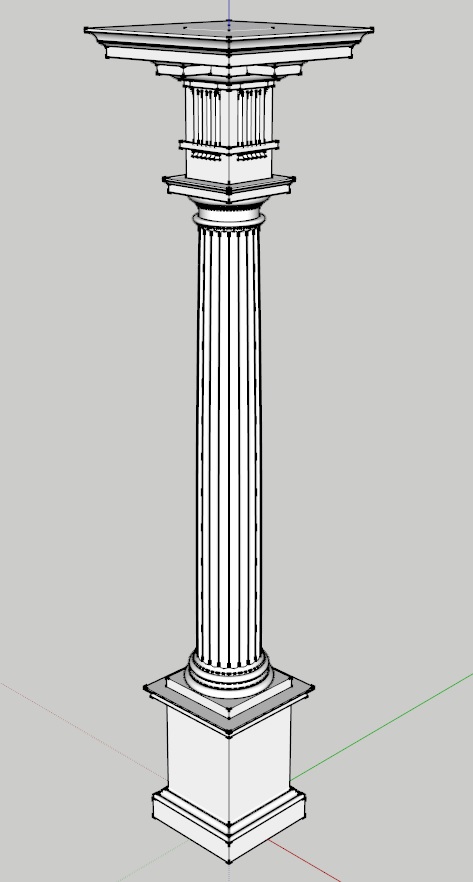
The Mutular Doric Order of Sir William Chambers
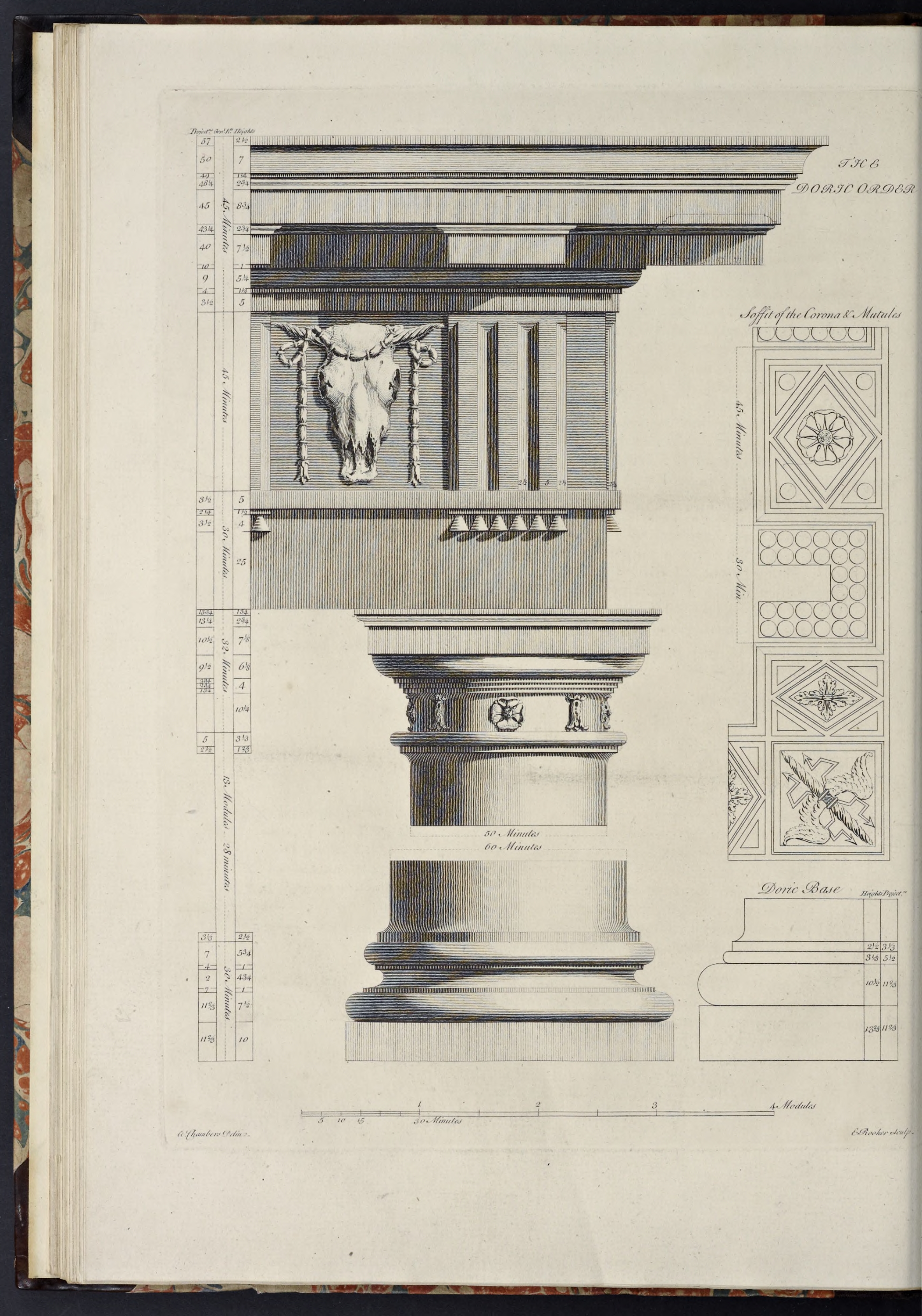
Chambers’ Doric Mutular order features an entablature derived from Vignola, his being composed in a greater style, and in a manner more characteristic of the order, than any other
, combined with a column capital derived from the Theater of Marcellus in Rome, from which in the form and dimensions of the particular members, I have deviated but little.
- The column height is 480 min, and the entablature height is 120 min, thus making the order 600 min high.
- The Capital is 32 minutes high and the Base is 27
1/2 minutes high, thus making the Shaft 4201/2 minutes high. - The pedestal is 144 min high, thus making the order with the pedestal 744 min high.
- and, as with all Chambers’ orders, the lower diameter is 60 minutes, and the upper diameter is 50 minutes, making the diminution one-sixth of the column diameter.
Create the Order Profiles
- Start in parallel projection, front view
- Set a guide 30 min to the right of the Centerline (for the lower diameter), and another 11
2/3 min to the right of that (for the projection of the plinth & pedestal die)
The Pedestal Profiles
The Doric pedestal of Chambers is a little more elaborate than the Tuscan, but is divided and formed in the same way.
- Set a guide 144 min up from the Baseline (for the height of the pedestal)
- Set guides horizontally and vertically on the Origin point (forming the bottom of the pedestal and the axis of the order)
- Draw a rectangle from the guides marking the Centerline and top of the pedestal down and out to the guides marking the bottom of the pedestal and projection of the die
- Double-click the face just created, right-click, make component
Pedestal-Die-profile - Set guides, going up from the bottom of the die, for 21
1/3 min, 4 min, 1 min, 41/3 min, and 11/3 min (for the pedestal plinth, torus, fillet, cyma recta, and fillet) - Set guides, all going out from the die, for 10
2/3 min, 72/3 min, and 2 min (for the plinth, torus, fillet under the cyma recta, and fillet under the top congé) - Draw a line, from the bottom-right corner of the die out to the last guide, then up to the next guide (for the plinth)
- Set a guide half the height of the torus inwards from the last projection guide, and draw a line from the last endpoint inwards to the intersection of the new guide with the top of the plinth
- Use the last endpoint as the start point for the bottom of a torus, using the guide above it as the height, then erase the new guide created above
- Draw a line, form the top endpoint of the arc, leftwards on the Red Axis to the next guide, then up to the next guide, then diagonally upwards and inwards to the next intersecting guides, then up to the next guide (forming a stand-in construction line for the cyma recta, and for the fillets above and below it)
- From the last endpoint, draw a congé going upwards and leftwards connecting it to the die
- Draw a line from the top of the congé down to the bottom of the pedestal
- Double-click the face just created and make it a component
Pedestal-Base-Molding-profile - Replace the stand-in diagonal line with an upside down cyma recta
- Erase the guides to the right of the die, and below the top of the pedestal
- Set guides, going down on the Blue Axis from the top of the pedestal, for 1
1/2 min, 31/6 min, 51/3 min,1/3 min, 41/2 min, and 11/6 min heights (for the crowning fillet, cyma reversa, corona, fillet, ovolo, and fillet) - Set guides, going out on the Red Axis and again all from the die, for 1 min, 5 min, 5
2/3 min, 102/3 min, 111/3 min, 141/3 min, and 15 min projections (for the fillet, ovolo, fillet, corona, cyma reversa, and crowning fillet of the pedestal cap) - Draw a line, from the top-right corner of the die, out to the guide marking the greatest projection of the pedestal cap, then down to the next guide, and then in to the next guide (forming the crowning fillet for the cap)
- Draw a diagonal line from the last endpoint downwards and inwards to the next intersecting guides (forming a stand-in for the cyma reversa)
- Draw a line, from the last endpoint, in to the next guide, then down to the next guide, then in to the next guide (forming the corona of the cap)
- Continue the line down to the next guide, then in to the next guide (forming the fillet over the ovolo)
- Draw a diagonal line from the last endpoint downwards and inwards to the next guide, then down to the next guide (forming a stand-in for the ovolo)
- From the last endpoint, draw a congé inwards and downwards to the die
- Draw a line, from the bottom of the congé up to the top of the pedestal
- Double-click the face just created and make it a component
Pedestal-Cap-Molding-profile - Replace the top stand-in diagonal line with a cyma reversa, and the bottom one with an ovolo
- Erase the guides to the right of the die and below the top of the pedestal
The Pedestal Die Profile
The Pedestal Base Profile
The Doric pedestal base is formed of a plinth at the bottom, topped by a small torus, over which is a fillet, which supports an upside down cyma recta, topped by another fillet, that merges into the die with a congé.
The Pedestal Cap Profile
The Doric pedestal cap is formed of a fillet, connected to the die with a congé, the fillet topped by an ovolo capped by a fillet, over which is the corona, which supports a cyma reversa crowned by a fillet.
The Column Base Profiles
- Set Guides, going up from the top of the pedestal, for 13
1/3 min, 101/2 min, and 31/3 min heights (for the Plinth, Torus, and Astragal) - Draw a Rectangle, from the Guides marking the Centerline and height of the Plinth downwards and outwards to the top of the pedestal and projection of the plinth
- Double-Click the Face just created and make it a Component
Column-Base-Plinth-profile - Draw a Torus above the Plinth, going backwards towards the Centerline from the projection of the Plinth
- Set a Guide, going out from the Lower Diameter, for 5
1/2 min, for the projection of the Astragal - Draw a Line, from the Endpoint of the top of the Torus arc just created, back to the next Guide, then use that Endpoint as the start for drawing an Astragal up to the next Guide
- From the top Endpoint of the Astragal, draw a Line inwards to the Centerline, then down to the top of the Plinth, then out to the Endpoint of the bottom of the Torus arc
- Double-Click the Face and make it a Component
Column-Base-Torus-profile - Erase any Guides below the top of the Base, and to the right of the Lower Diameter
The Column Base Plinth Profile
The Column Base Torus Profile
The Column Shaft Profile
The Doric Column Shaft follows the same pattern as the Tuscan (as, indeed, do the Shafts of all the Orders).
- Set a Guide 420
1/2 min up from the top of the Base (for the height of the Shaft) - Set a Guide 2
1/2 min up from the bottom of the Shaft (for the Lower Cincture) - Set a Guide 3
1/3 min out from the Lower Diameter (for the Lower Cincture) - Draw a Line, from the Intersection of the Centerline and the top of the Base, out to the Guide marking the Lower Cincture projection, then continue it up to the next Guide
- Draw a Congé, from the last Endpoint, up and in to the Guide marking the Lower Diameter (thus completing the Lower Cincture of the Column)
- Erase the Guides to the right of the Lower Diameter and below the Congé just drawn
- Now go back and draw a Line, from the intersection of the top of the Base and the Centerline, up on the Blue Axis to the Guide marking the top of the Shaft (forming the Column Centerline)
- Set Guides 3
1/3 and 11/3 min down from the top of the Shaft (for the Astragal and Upper Cincture) - Set a Guide 25 min out from the Centerline (for the Upper Diameter)
- Set a Guide 2
1/2 min out from the Upper Diameter (for the Upper Cincture; the Astragal will project equal to the Lower Diameter) - Draw a Line from the last Endpoint (at the top of the Shaft Centerline) outwards to the Guide marking the Lower Diameter, then use the Endpoint of that Line as the projection and top of the Astragal, which you will draw going down to the next Guide
- Draw a Line, from the bottom Endpoint of the Astragal, inwards to the next Guide, then down to the next Guide
- Draw a Congé, from the last Endpoint, down and in to the Guide marking the Upper Diameter (thus completing the Upper Cincture)
- Erase the Guides marking the height and projection of the Upper Cincture (leaving the Guides marking the Upper & Lower Diameters)
- Draw a temporary diagonal line connecting the endpoints of the two congé moldings (or connecting the start & stop points for applying entasis, as explained below)
- Double-click the face just created and make it a component
Column-Shaft-profile - Finish by applying entasis to the shaft profile
- Erase the guide marking the lower diameter
The Column Capital Profiles
The Doric Capital of Chambers is similar to the Tuscan, with a Necking (again equal to the Upper Diameter), connecting with a Congé to the lowest of three Fillets rising in step-fashion over it, which supports an Ovolo, on which sits the square Fascia of the Abacus, which is topped with a Cymatium formed of a Cyma Reversa molding and crowning Fillet.
- Set a Guide 32 min up from the top of the Shaft (for the height of the Capital)
- Set Guides, coming down from the Guide just made, for 1
3/4 min, 23/4 , and 71/8 min heights (for the Fillet & Cyma Reversa of the Abacus Cymatium, and Fascia (or Core) of the Abacus) - Set Guides, going out from the Upper Diameter, for 10
1/2 , 11 min, 131/4 , and 133/4 min projections (for the Fascia of the Abacus, the beginning and ending reveals of the Cyma Reversa, and Fillet) - Draw a Rectangle, from the Guides marking the top of the Capital and the Centerline, downwards and outwards to the Guides marking the bottom and projection of the Fascia of the Abacus
- Double-Click the Face just created and make it a Component
Column-Capital-Abacus-Fascia-Core-profile - Draw a Line from the top right corner of the Abacus Fascia outwards to the Guide marking the projection of the Fillet, then down to the next Guide
- Draw a Line from the last Endpoint inwards to the next Guide, then draw a diagonal Line downwards and inwards to the next Guide, then in to the next Guide, then up to the top of the Abacus
- Double-Click the Face just created and make it a Component
Column-Capital-Abacus-Cymatium-Molding-profile - Replace the stand-in diagonal line with a Cyma Reversa
- Erase the Guides to the right of the Upper Diameter
- Set Guides, coming down from the bottom of the Abacus, for 6
1/8 min, and 4 min heights (for the Ovolo, and the three Annulets under it; the Necking occupying the remaining 101/4 min down to the top of the Shaft) - Set Guides, going out from the Upper Diameter, for 1
3/4 min, 23/4 min, 33/4 min, and 91/2 min projections (for the 1st, 2nd & 3rd Annulets, and the Ovolo) - From the bottom-left of the Abacus Fascia, draw a Line going out rightwards to the last Guide, then draw a diagonal Line downwards and inwards to the nearest Guide intersection (this forms a stand-in line for the Ovolo)
- Draw a construction Line from the last Endpoint down to the Guide marking the top of the Necking and divide it into 3 parts, setting Guides at the two divisions
- Draw a Line from the bottom of the 1st divided part in to the next Guide, then down to the next Guide, then continue the Line in to the next Guide, then down to the next Guide
- Erase the two lower (unused) construction Line parts
- Draw a Congé going inwards from the last Endpoint down to the Guide marking the Upper Diameter
- Draw a Line from the bottom of the Congé down to the top of the Shaft, then inwards to the Centerline, then upwards to the bottom of the Abacus Fascia
- Double-Click the Face just created and make it a Component
Column-Capital-Ovolo-profile - Replace the stand-in diagonal line with an Ovolo
- Erase the Guides to the right of that marking the Upper Diameter, and below the top of the Capital
The Capital Abacus Fascia Profile
The Capital Abacus Cymatium Profile
The Capital Ovolo Profile
The Entablature Profiles
The Doric Entablature of Chambers follows the standard Doric division of having the Architrave height equal 30 min (or 1 module), and the Frieze equal 45 min (or 1
- Set Guides, starting from the top of the Capital and going up on the Blue Axis, for 30 min, 45 min, and 45 min heights (for the tops of the Architrave, Frieze, and Cornice)
- Draw a Rectangle, from the Guides marking the Centerline and top of the Cornice downwards to the Guides marking the top of the Capital and the Upper Diameter
- Double-Click the Face just created and make it a Component
Entablature-Frieze-Core-profile - Set a Guide, coming down from the Guide marking the top of the Architrave, for 5 min (for the height of the Architrave Tenia)
- Set a Guide 3
1/2 min out from the Upper Diameter (for the projection of the Tenia) - Draw a Rectangle the height and projection of the Tenia (as noted by the Guides) coming out from the Upper Diameter
- Double-Click the Face just created and make it a Component
Entablature-Architrave-Tenia-profile - Erase the Guides marking the bottom and projection of the Tenia
- Set Guides, going up from the Guide marking the bottom of the Cornice, for 5 min, 1
1/4 min, 51/4 min, 81/2 min, 23/4 min, 83/4 min, 23/4 min, 11/4 min, and 7 min heights (for the Capital of the Triglyph, the Fillet, Ovolo, Mutule Fascia, Cyma Reversa, Corona, Cyma Reversa, Fillet, and Cavetto, with the remainder going to the crowning Fillet) - Set Guides, going out from the Frieze Core, for
3/4 min, 4 min, 9 min, 10 min, 103/4 min, 131/4 min, 45 min, 453/4 min, 481/4 min, 49 min, 50 min, and 57 min projections (for the Capital of the Triglyph when over the Metopes, the Fillet, Ovolo, Mutule Fascia, bottom reveal of the Cyma Reversa, top of the Cyma Reversa, Corona, bottom of the Cyma Reversa, top of the Cyma Reversa, Fillet, bottom of the Cavetto, and Fillet) - Draw a Line, from the upper-right corner of the Freize Core, out on the Red Axis to the last Guide, then go down to the next Guide (forming the crowning Fillet of the Cornice)
- From the last Endpoint, draw a diagonal Line inwards and downwards to the next Guides (creating the stand-in line for the Cavetto)
- Continue the Line in to the next Guide, then down to the next Guide, then in to the next Guide (for the Fillet under the Cavetto and the top reveal of the Cyma Reversa)
- Draw a diagonal Line downwards and inwards to the next Guide intersection (as a stand-in for the Cyma Reversa)
- From the last Endpoint continue the Line in to the next Guide, then down to the next Guide, then in to the next Guide (forming the Fascia of the Corona)
- Draw a diagonal Line, from the last Endpoint, downwards and inwards to the next Guide, then in to the next Guide (making the stand-in line for the Mutule Cymatium where it lies above the Mutule Fascia, and it’s beginning reveal)
- From the last Endpoint, draw a Line down to the next Guide, then in to the next Guide (for the Mutule Fascia)
- Draw a diagonal Line, from the last Endpoint, downwards and inwards to the next Guide, then down to the next Guide, and in to the next Guide (for the Ovolo and Fillet under it)
- Then continue the Line down to the next Guide, in to the next Guide, then up to the top of the Cornice (for the Capital of the Triglyph over the Metopes)
- Double-Click the Face just created and make it a Component
Entablature-Cornice-Molding-profile - Replace the lowest stand-in diagonal line with an Ovolo, the next two small diagonal lines with Cyma Reversa moldings, and the last diagonal line with a Cavetto
- Erase all the guides, unhide all the components (if you hid any) and Zoom Extents
The Entablature Frieze Profile
The Architrave Profile
Chambers’ Architrave features a single Fascia, topped by a large Fillet (called the Tenia), under which are thin rectangular projections called Regula (in-line with the Triglyphs of the Frieze), from which hang six Guttae (or conical drops).
The only continuous element in this Architrave is the Tenia, as the Regula is the same width as the Triglyphs. Therefore the Tenia will act as the Architrave molding, and the other elements will be created separately later on in the process, along with the Triglyphs & Metopes.
The Cornice Profile
Chambers exemplar Doric Cornice follows the Mutular design adopted by Vignola, and featured earlier in the works of Donato Bramante and Sebastiano Serlio. In form it has a large Fillet above the Frieze (called the Capital of the Triglyph), breaking forward above the Triglyphs, topped by a smaller unbroken Fillet, over which is an Ovolo supporting the Mutule Fascia, out of which project the large rectangular Mutules (which have Guttae recessed into their bottoms), both being capped by a Cyma Reversa band wrapping around the individual members. Over this is the Corona, whose Soffit is decorated with recessed sculptured panels between the Mutules, and is itself topped by a Cyma Reversa which supports another Fillet, under a large Cavetto and crowning Fillet.
The construction of this Cornice will be the same as for the Architrave & Frieze, involving the creation of the Profile to use with Follow-Me, with the repeating elements being created afterward.
The Mutule Fascia and it’s Cymatium are going to be created as part of the main Profile, however the Mutules themselves (with their own Cymatium) will be projecting in front of this at regular intervals. Rather than having to worry about breaking the Fascia & Cymatium where the Mutules are placed, they are going to be kept continuous and the Mutules will simply back-up into them. Though this adds more geometry to the model, in my opinion the advantages in forming the Cornice in this way outweigh the disadvantages.
I will be constructing the Capital of the Triglyph in the same fashion, with the portion over the Metopes part of the main Profile, and the parts breaking forward over the Triglyphs being part of the repeating elements.
Form the 3D Elements
With the Doric Order, the construction becomes more complex. While some of the profiles can be used as is to construct various 3D elements of the order, such as the pedestal & column, the entablature will need additional elements created in order to become full-fledged Doric elements. This will be handled below.
The Standalone Pedestal
- Hide all the components except those for the pedestal profiles
- Copy the three pedestal components into memory, hide the originals, Paste-in-Place the copies, Right-click on the components, Make Unique, and rename
- Open the
Pedestal-Die-standalone , and turn it into a square component, then close the component - Now wrap the cap & base moldings around the die core
- Select all three pedestal components and make a standalone component
Pedestal-standalone
The standalone pedestal is formed by wrapping the molding components around the central core component.
The Pedestal Die
The Pedestal Cap & Base Moldings
The Pedestal
The Column Base Plinth
The following method for using the Push/Pull Tool on the Base Plinth is going to be applicable to all the remaining Orders, as they all use the same base projection.
- Unhide the Base Plinth Profile Component, Copy it into memory, Hide the original, Paste-in-Place, Right-Click, Make Unique, and Rename
Column-Base-Plinth - Open the component, and Push/Pull the face forward, sideways and backwards an amount equal to it’s width (as it is a perfect square)
- Hide the Base Plinth Component
The Cylindrical Components of the Column
Creating the cylindrical elements of the Doric Column (Base Torus, Shaft, & Capital Ovolo) is done the same way as for the Tuscan Column.
- Unhide the Profiles, Select all three, Copy into memory, Hide the originals, Paste-in-Place, and rename (I replace “profile” with “wedge”)
- Turn each of the copied components into a wedge-based cylinder by creating 20 wedges of 18 degrees each, which are then Rotated & Copied to form the cylinder
- In Front view, select all the individual wedge components of each element and combine into single
Column-Base-Torus ,Column-Shaft &Column-Capital-Ovolo components as appropriate - Hide the three cylindrical components just created
The Column Capital Abacus
The Doric Abacus differs from the Tuscan in its complexity, with a Cyma Reversa & Fillet replacing the simple Congé & Fillet of the Tuscan Capital, so therefore was created as two Components (a Core & Molding), and, as such, can be created the same way the Pedestal was, by using the Push/Pull Tool on the Core Component, then wrapping the Moldings around it with Follow-Me.
- Unhide the
Column-Capital-Abacus-Fascia-Core-profile component, copy it into memory, hide the original, Paste-in-Place, Right-click, Make Unique, and renameColumn-Capital-Abacus-Fascia-Core - Unhide the
Column-Capital-Abacus-Cymatium-Molding-profile component, copy it into memory, hide the original, Paste-in-Place, Right-click, Make Unique, and renameColumn-Capital-Abacus-Cymatium-Molding
The Column Capital Abacus Fascia
The Column Capital Abacus Cymatium
The Standalone Column
With both the square and cylindrical elements of the Column formed, now you can Select the Base Plinth & Torus, Column Shaft, and Capital Ovolo & Abacus elements, and combine them into a single column component.
- Unhide the
Column-Base-Plinth ,Column-Base-Torus ,Column-Shaft ,Column-Capital-Ovolo &Column-Capital-Abacus , and join them together into a singleColumn-standalone - Hide the new component
The Entablature Repeating Elements
Unlike the Tuscan, the Doric Entablature features repeating elements, and, unlike any of the other orders, these occur in all three parts of the Entablature:
- The Frieze contains what are the most recognizable repeating elements, the Triglyphs, separated from each other by square spaces called Metopes, usually decorated with bas-reliefs of different kinds.
- The Architrave contains the Regula, located directly below the Triglyphs under the Tenia, and the row of six Guttae that hang down from each Regula.
- The Cornice contains the projecting Capital of the Triglyph (where it breaks over and around the Triglyphs), the block-like Mutules hanging down from the Soffit of the Corona directly over the Triglyphs, and finally the sunken panels and bas-reliefs of the Soffit in the underside of the Corona.
Therefore, once the three main parts have been formed, their profiles will then be reused to help form the repeating elements, which will then be put in place.
- Unhide the Entablature Profiles (Architrave, Frieze, & Cornice), Copy the Components, Hide the originals, Paste-in-Place, Make Unique, and Rename (as with the Pedestal, I change “profile#1” to “standalone”)
- Open the Frieze Core component, Push/Pull the Face forwards 25 min (Chambers’ standard dimension for the Upper Diameter), then repeat on the new left & back Faces
- Use the Follow-Me Tool to wrap the Moldings (Architrave aka Tenia & Cornice) around the Frieze Core
- Close & hide the components just created, and unhide the entablature profiles
The Triglyph Of The Frieze
As the most recognizable, and perhaps important, repeating element, I'll deal with the Triglyph first, as it will govern the elements in both the Architrave and Cornice.
The Triglyph is composed of three ‘beams’, chamfered on their sides and where they join to a ‘half-beam’ at the top. It is usually equal in width to a Semidiameter and centered over each Column and separated from each other by square spaces called Metopes.
In Chambers’ Treatise, he follows Palladio, Perrault & Gibbs in having the side chamfers of the Triglyph end in a right angle to the top beam, the same as the inner chamfers. However, Serlio & Vignola treat the side chamfers differently, having them curve upwards to the front outside corner, Serlio’s going to the very top, and Vignola’s terminating at the same height as the straight inner chamfers.
- Start with Guides set at the heights of the top & bottom of the Frieze
- Set 6 Guides 2
1/2 min apart (giving 6 divisions totaling 15 min), coming out from the Centerline of the Column rightwards on the Red Axis (this establishes the divisions of the 21/2 min ‘half-beams’ of the Triglyph on this side of the Centerline) - Set 2 Guides 2
1/2 min apart, coming downwards from the top of the Frieze on the Blue Axis (this establishes the top fascia and chamfer of the half-beam across the top of the Triglyph - Draw a Rectangle, starting at the top right Intersection of the Guides marking the top of the Frieze and outside edge of the Triglyph, going leftwards to the third Guide inwards from the right and the bottom of the Frieze, so you have one Guide running down the middle of the rectangle (which should thus be 5 min wide and thus forms one of the beams of the Triglyph)
- Draw a Line, starting from the Intersection of the outside right edge of the rectangle and the Guide right below that of the top of the Frieze, inwards to the next Guide, then down along the middle Guide to the bottom of the rectangle (this forms an elevation of one of the beams)
- Switching to Isometric View, and using the Push/Pull Tool, pull the Face of the upside-down L-shape out 2
1/2 min, giving you an upside-down L-shaped Fascia - At the top of the Triglyph beam, draw a Line, from the bottom right corner of the front of the short end of the Fascia (the same as the bottom left corner of the side of the top of the Fascia), downwards and backwards to the Intersection of the Guide just below it and the side of the Triglyph (thus forming a triangle on the right side of the Geometry)
- From the last Endpoint, draw another Line back upwards and frontwards to the inner corner of the Fascia (thus forming the sloping diagonal Face of the top bevel)
- At the bottom of the Triglyph beam draw a Line from the bottom-right corner of the pulled out long end of the Fascia leftwards and backwards to the bottom-right corner of the Geometry (thus forming another triangle along with the sloping face of the side bevel)
- Erase the unnecessary lines in the Triglyph by Erasing the lines on the bottom and side of the beam going backwards from the angles of the bevels, as well as the center line on the back, and the two short lines (one heading outwards and one frontwards) that are attached to it at its top)
- Triple-Click the Geometry to select the whole grouping and Move it forwards, on the Green Axis,
1/4 min, and then Push/Pull the rear Face of the beam backwards on the Green Axis1/4 min (thus forming the ‘reveal’ that raises the bevels beyond the flat of the Frieze); there will be a small line you need to Erase, extending from the bottom corner of the top bevel angle back to the face you just moved - Triple-Click the Geometry, and make it a Group (for ease of moving)
- Back in Front View, Select the Group, and Move/Copy it towards the Centerline, either 5 min or from its right top corner to its left top corner, and make 5 copies
- Select the 2nd, 4th, & 6th Groups from the right, and Right-Click on them and choose ‘Flip Along - Red Direction’
- Select all six Groups and join them into a Component
Entablature-Triglyph - Open the new Component, Explode the individual Groups, and clean up unwanted Edges running through the centers of the fascias and bevels
The Regula And Guttae Of The Architrave
As noted earlier, the Regula and Guttae hang just below the Triglyph, under the Tenia.
- Set Guides equal to the bottom of the Tenia of the Architrave, one 1
1/2 min further down, and another one 4 min further down from that (for the Regula and Guttae heights) - Set Guides 2
1/4 min and 31/2 min, out from the Upper Diameter (establishing the projections of the Regula and Guttae on the Red Axis) - Under the Architrave Molding Profile (the Tenia) created earlier, draw a Rectangle, from the bottom-left corner of the Tenia Profile, downwards and rightwards to the first intersecting Guides (marking the bottom & projection of the Regula)
- Double-Click this rectangle to Select it, and make it a Component
Entablature-Regula-profile - Move/Copy the new Component towards the Centerline, so the edge that was formerly on the Upper Diameter is now on the Guide marking the projection (or right edge) of the Triglyph, then Right-Click, Make Unique, and Rename
Entablature-Regula - Rotate the moved Component 90 degrees clockwise towards the Front (keeping the left edge in place on the Guide)
- Open the Component, and use the Push/Pull Tool to extend the Regula Face inwards and past the Centerline for a total of 30 min (which is equal to the width of the Triglyph over it)
- Close and Hide the new Component
- Draw a Line, from the Guides marking the right side of the Triglyph and the bottom of the Guttae, inwards two Guides (or 5 min); then continue it diagonally upwards and rightwards to the second Guide intersection above it (at the height of the bottom of the Tenia); then finish the profile by drawing a Line downwards to the beginning of the first line you just drew
- Double-Click the Face just created and make it a Component
Entablature-Guttae-elevation - Move/Copy the Component outwards to the right so it’s bottom right corner is at the Guides marking the bottom and projection of the Guttae
- With the shape formed as you prefer, Open the Component (either the original or the copy), and draw a Line from the left side of the triangle over to the right side along the Guide marking the bottom of the Regula, then Erase the smaller upper triangle, and Close the Component
- Right-Click on the Moved/Copied Component, Make Unique, and Rename
Entablature-Guttae-profile - Select the Guttae Elevation, Copy it into memory, Hide it, Paste-in-Place, Right-Click, Make Unique, and Rename
Entablature-Guttae - Open the new Component and draw a Line from the Midpoint of the bottom of the truncated triangle up to the top, then Erase the left portion of it
- Draw a Circle (in Isometric View and flat on the Red/Green Plane) with its center at the left bottom corner of the truncated triangle and its radius equal to the width of the bottom, and Erase the Face of the Circle
- Select the Edge of the Circle, activate the Follow-Me Tool, and click on the Guttae Face, then Close and temporarily Hide the Guttae Component
- Unhide the Guttae Elevation, Open it, Double-Click the Face, Copy it into memory, then Close & Hide the Component
- Paste-in-Place the copied Geometry, and enlarge the Face so it extends beyond the shape of the Guttae on all sides of the Red & Blue Axis, then Cut/Copy it into memory
- Unhide the Guttae Component, Open it, and Paste-in-Place
- Select All in the Component, Right-Click, and choose Intersect Faces - With Selection
- Erase the Edges of the truncated triangular Face, then select the back curve of the Guttae and Erase that; finish by Erasing the remaining arcs at top and bottom of the back, then Close the Component
- Go back to the Guttae Profile Component, Open it, and draw a Line from the Midpoint of the bottom to the Midpoint of the Top, and Erase the left half
- Measure the distance between the vertical line of the Profile Component and the Upper Diameter (in this case it is 1 min)
- Now Move the Left Edge of the Face leftwards till it reaches the Guide marking the Upper Diameter, then Close the Component
- Open the Guttae Component, and use the Push/Pull Tool to extend the back Face of the Guttae backwards on the Green Axis the distance you just measured (and Hide the two Lines that will appear where the curved front meets the straight sides when finished)
- Close the Component, and Move it the same distance towards the front (on the Green Axis) as you Pushed/Pulled the back outwards earlier so the back of the Guttae is even with the Origin on the Red Axis
- Select the Guttae component, and Move/Copy it inwards towards the Centerline 5 min and make 5 copies (so that the 6 resulting Guttae are aligned evenly under the Regula & Triglyph)
The Regula
The Regula is essentially a Fillet, equal in width to the Triglyph, and on the front projecting out the same amount as the Triglyph (at least in Chambers’ design, other Authorities have the two elements project outwards at different amounts).
The Guttae
The Guttae are six ‘Drops’ that hang below the Regula (and also from the bottom of the Mutules, which will be discussed later) and align along the bottom of the Triglyph, two drops to each beam.
In his Treatise Chambers specifies that they are conical in section, stating not pyramidal, as they are improperly made by most of our English workmen
.
The Capital Of The Triglyph
The Capital of the Triglyph is actually just a Fillet that is at the bottom of the Cornice, the only distinguishing feature being that it breaks around the Triglyphs to form a ‘cap’, so seems more a part of the Frieze.
The Mutule Of The Cornice
The Mutule is essentially a bracket, which features cylindrical or conical Guttae hanging down from it, and placed in direct line with the Triglyphs of the Frieze.
In the Greek Doric it was simply a flat slab, hanging down at an angle from the Soffit, and this is how it appears in the work of Serlio & Palladio, as well as in the Denticular Doric of Vignola, though they have the entire Soffit angled, without the Mutules separated from it.
Serlio showed an alternative form used by Bramante in the Cortile of the Vatican (apparently based on Ancient Roman examples), where the panel with the Guttae hangs down below the Soffit in a box-like form, which Vignola adopted and is the form shown by Chambers.
The form of this box-like Mutule varies, with Vignola showing it being equal in width to the Triglyph but with the lower parts of the sides open to show the Guttae drops hanging down (thus allowing the Guttae in the Mutule to match the size of the Guttae under the Regula). A similar design was shown by both Freart de Chambray and Batty Langley, with the Mutule having a solid upper part (with either just the Cymatium or a Cymatium & narrow Fascia) and full Guttae hanging down, visible from both front & sides. Le Clerc & Gibbs made the Mutule width equal the Capital of the Triglyph, thus allowing the two sets of Guttae to still match but allowing the Mutule to have solid sides all the way down. Chambers, on the other hand, adopts the box-like rectangle, with sides all the way down, but sets the width to that of the Triglyphs, the result of which is that the Guttae are somewhat smaller than those under the Regula. I will follow the latter form here, but the others can be used equally easily if you wish, with minor alterations to the instructions below.
- Set a Guide at the top of the Mutule Band (the bottom of the Mutule Cymatium), and another 7
1/2 min below it (to establish the bottom of the Mutules themselves, which leaves a 1 min reveal under the Mutules) - Draw a Rectangle, from the Guides marking the top of the Mutule Band and the width of the Triglyph, inwards and downwards to the Guides marking the Centerline and bottom of the Mutules
- Use the Push/Pull Tool to bring the the Face out towards the front on the Green Axis 30 min (this will form half of the finished Mutule)
- Select the front, rear, and right Edges of the bottom Face of the Mutule, then use the Offset Tool to come in towards the center of the Face by 1 min (this method will offset just the three surrounding faces and leave alone the edge that is going to become the centerline of our Mutule)
- Select the long centerline of the Mutule and Divide it into 6 parts, then Select the short front line (not the outer Edge) and Divide that into 3 parts (this establishes the grid to draw and layout the Drops)
- Set a series of Guides at the divisions you just created along both the Red and Green Axes (this will setup a grid showing where the Guttae will be located)
- In the front left square defined by the Guides you just created, set a pair of Guides running diagonally from each corner to get the center of the resulting square (to establish the center where the drop will be created)
- Draw a Circle centered on the Guide Intersection you just made, with a radius of 2 min, then Erase the diagonal Guides
- Double-Click the Face of the circle and make it a Component, being sure to change the option ‘Glue to: Any’ to ‘Glue to: None’,
Entablature-Mutule-Guttae - Select the Guttae Component just made and Move/Copy it from the Midpoint of the short line in front of it (on the Green Axis) to the Midpoint of the short line to its right, and repeat again to the Midpoint of the next line over (thus creating a row of three Guttae across the front of the Soffit of the Mutule)
- Select the three Guttae Components and Move/Copy them from the Midpoint of the short line to their left (even with the Centerline of the Column) backwards to the Midpoint of the short line behind them (on the Green Axis)
- Select the 4 Guttae (2 rows of 2 Guttae) in the front right corner of the Bottom of the Mutule, and Move/Copy them backwards to fill the 8 sections of the grid immediately behind them (leaving the 4 spaces in the grid next to the Centerline empty)
- Draw a Rectangle around the 4 empty grids at the rear center of the Mutule bottom, then Erase the edge at the back/bottom (thus joining the new Face to the bottom of the ‘walls’ of the Mutule)
- Select the Face of the Soffit of the Mutule immediately surrounding the Guttae and use Push/Pull to move it upwards 2 min (thus leaving the Drops, central block and ‘walls’ hanging down)
- Select one of the Guttae Components and Move/Copy it out a short distance
- Open the Component and use the Push/Pull Tool to extend it upwards 2 min, then Double-Click the top Face of the Guttae, and activate the Scale Tool; while holding Ctrl & Shift scale the top down by about 0.75 to produce a conical shape, then Close the Component and Erase the extra copy you were working on
- With half the Mutule block done, switch to Front View, Select all the Mutule Geometry and Move/Copy it leftwards on the Red Axis far enough so it can’t interfere with the original
- Right-Click on the Selected Geometry and choose ‘Flip Along Red Direction’
- Move the Selected Geometry back rightwards till it joins with the original (and thus gives you a full Mutule block)
- Triple-Click on the Mutule to Select all the Edges and Faces and make them a Component
Entablature-Mutule-Core - Select all of the Mutule Geometry, Right-Click and choose ‘Intersect Faces With Selection’
- Hide the Frieze Core and the Guttae hanging down from the Mutule
- Open the Mutule Core, and Erase any extraneous lines running through the Faces, then Close the Component
- Open the Cornice Molding Profile Component, and Copy into memory the Mutule Cymatium profile line and arcs that are located between the Mutule Band and Corona of the Profile, then Close and Hide the Component
- Paste-in-Place the copied profile and then Move them left on the Red Axis till the Endpoint of the short horizontal line reaches the top back right corner of the Mutule Core Component
- Draw a pair of Lines from the bottom of the short line up to a point even with the top of the curve, then over to its Endpoint, to create a Face for the Cyma Reversa molding
- Double-Click the Face just created and make it a Component
Entablature-Mutule-Cymatium - Open the Mutule Core Component and Select the front and two side Edges, Copy them into memory, then Close the Component
- Open the Mutule Cymatium Component, Paste-in-Place, activate the Follow-Me Tool, and click on the Cymatium Face; then Close the Component
- Unhide all the Components
- Select all the elements of the Mutule (the Core, Cymatium, and 28 (or 36 if you didn’t add the central block) Guttae, and make them a Component
Entablature-Mutule
Assemble The Repeating Elements Component
Since all of the repeating elements of this Entablature are aligned in relation to each other, it makes sense to arrange and join them together into one Component so they can be Moved/Copied together.
- As the Mutule is not exactly above the Triglyph, but forward a little due to the projection of the intervening elements, it needs to be moved into position, so measure the distance on the Cornice Profile from the Upper Diameter out to the edge of the Mutule Band (in this example it is 10 min)
- Move the Mutule Component out towards the front on the Green Axis the amount just measured (this will place it in its proper position over the Triglyph, etc)
- Select the Mutule, Capital of the Triglyph, Triglyph, Regula & six Guttae components, and make them into a single Component
Entablature-RepeatingElements - Right-Click on the Component just created and Choose Change Axes, and set the new Axes at the Intersection of the Centerline and bottom of the Architrave (this will facilitate placing it on the finished model easier)
- Now you can Move the new Component 25 min out towards the front on the Green Axis, which will place the Component in the correct location for a standalone Entablature
- At this point you can Erase all the Guides, as they are mostly not needed for the final steps to finish the Entablature
The Soffit of the Doric Entablature
The Soffit of the Doric Entablature, located on the underside of the Corona, is, unlike the Tuscan, always decorated more elaborately than with a simple drip cap.
Serlio shows panels filled with back-to-back winged thunderbolts (which are a common Classical symbol alluding to the Greek/Roman God Zeus/Jupiter) between the Mutule panels in his example, and diamond-shaped panels filled with foliate ornament and with a circular form in each corner in his portrayal of the Soffit of the Doric Order of the Theatre of Marcellus.
Palladio shows his Soffit having panels of the same size as his Mutules above the Metopes, filled with diamond-shaped recesses, wrapped in moldings, and filled with foliate ornament and with a circular drop in each corner, a design also appearing in the square panels at the corner of his Soffit and between the corner and the closest Mutule panel, with the spaces between the Mutules and ornamented panels being filled with simple flat panels sunk up into the Soffit.
Vignola’s Denticular Soffit is similar to Palladio’s, though with more variety in the ornament, his rectangular panels filled with a Rose flanked by Fleur-de-Lys, his corner panels filled with only a Rose, and the larger panels flanking the corner panel filled with winged thunderbolts. In his Mutular version he shows even more variety, with the panels between the Mutules filled with a diamond-shaped recess enclosing a Rose and circular drops in the corner recesses outside the diamond, the filler panels between the corner panel and his Mutules having a diamond-shaped panel as well, this time filled with foliate ornament with the triangular corners plain, and his corner panel filled with a winged thunderbolt, all his panels wrapped with Cyma Recta moldings.
James Gibbs’ Soffit has sunken panels, surrounded by Cyma Recta moldings, with floriate ornament in all of them, surrounded by wide Fascias.
Chambers design, follows that of Vignola, with minor variations in the moldings wrapping the recesses.
As with the Mutules, Chambers provides only minimal dimensions for the Soffit, so a good deal of extrapolating has to be done. The only dimensions given on his plan are the widths of the Mutule (not including it’s Cymatium) and the Metopes (as measured from Mutule Fascia to Mutule Fascia), which are 30 & 45 min respectively. These dimensions are then combined with ones extrapolated from the Cornice Profile, such as that of the width of the flat Fillet surrounding all the panels, as that is the distance between the top of the Mutule Cymatium and the edge of the Corona Fascia, which in this example is 1
- Start by Hiding all the Components except the Cornice Molding Profile, and change your View to Isometric (so you can easily create lines on the Green Axis in ‘front’ of the Cornice Profile
- From the right bottom corner of the Corona draw a Line, coming out on the Green Axis towards you, extending 75 min, then Divide that line into 5 parts
- Set a Guide equal to the projection of the Mutule Band Cymatium, forming the rear edge of the Soffit
- Set a pair of Guides 1
3/4 min in towards the center of the Soffit from the Guide just made and your divided Line (this will represent the Fillet forming the actual Plane of the Soffit, at front and back) - Set Guides (coming out towards you along the Green Axis from the Cornice Profile) at the Endpoint of the first divided line, 3
1/4 min beyond that, then 13/4 min beyond that, and a final one at the Midpoint of the third divided part (these represent the Mutule Fascia, the Mutule Cymatium, the flat Fillet of the Soffit, and the Midpoint of the Soffit over the Metopes) - We now want to form a Plane surface for the Soffit over the Metopes, with narrow projections in front for the Fillets in front of the Mutules
- From the front right bottom corner of the Corona (on the Cornice Profile) draw a Line, going leftwards on the Red Axis back towards the Centerline, to the first Guide, then continue the Line frontwards out on the Green Axis to the second Guide, then continue the Line leftwards on the Red Axis back towards the Centerline to the last Guide, then continue the Line frontwards on the Green Axis out to the next Guide, then continue the Line rightwards on the Red Axis to the next Guide, then backwards along the Green Axis to the next Guide, then out rightwards on the Red Axis to the next Guide, then continue the Line frontwards on the Green Axis again to the next Guide, and finish by going right out on the Red Axis to connect it to the divided Line itself, forming a ‘backwards-h-shaped’ Face
- Erase all of the divided Line first created, and recreate the part along the front between the two short Lines (we want a solid Line there, not one with breaks in it)
- Double-Click the Face just created and make it a Group
- Select the Group just created, and Move/Copy it out frontwards along the Green Axis till it is clear of the existing Geometry, then Right-Click, and Flip Along the Green Direction, then Move it back till it is touching the original Geometry
- Explode the two Groups, and Erase the short Lines dividing the Midpoints of the Fillet, then Double-Click the Face and make a Component
Entablature-Soffit-Fillet-Metope - Now draw a Rectangle in the empty area within the Component just created, and which should be 28
1/4 by 35 min in size (representing the panels over the Metopes) - Double-Click the Face of the Rectangle just created and make it a Component
Entablature-Soffit-Panel-Metope - Set a Guide 75 min out frontwards of the Cornice Profile (to reach the end of the Fillet Component above)
- Set Guides, going frontwards along the Green Axis from the last Guide, for 18
1/4 min, 13/4 min, 181/4 min, 13/4 min, 281/4 min, and 13/4 min (for half of the Mutule plus it’s Cymatium, the Soffit Fillet, the intervening panel between the Mutule and corner, the Fillet, the corner panel, and the final Fillet to the front edge of the Soffit as it wraps around the corner) - Draw a Line from the Endpoint of the closest Soffit Metope Fillet (representing the front outer corner of the Corona Fascia) frontwards on the Green Axis to the last Guide you made (this should be 70 min out, this being 38
1/4 +13/4 +281/4 +13/4 min) - From the last Endpoint, draw a Line diagonally inwards and leftwards to the Guide intersection (representing the inner corner of the outer Fillet of the Soffit), then continue it backwards on the Green Axis to the next Guide, then leftwards on the Red Axis to the next Guide, then diagonally inwards to the Guide intersection (representing the outer corner of the Mutule Fascia Cymatium), then continue the Line backwards on the Green Axis to the second Guide, then turn rightwards on the Red Axis to the next Guide, then continue backwards on the Green Axis to the Metope Fillet, and finally end it by turning rightwards to the Endpoint of he first Line drawn, creating a Face for the Soffit Corner Fillet
- Now draw a Rectangle in the area within the Face just created that is bound by the Guides, and which should be 28
1/4 by 181/4 min in size (representing the intervening panels between the Corner Panels and Mutules) - Double-Click the Face of the Rectangle just created and make it a Component
Entablature-Soffit-Panel-Corner-Rectangle , making sure to change the option ‘Glue to: Any’ to ‘Glue to: None’, then Hide the Component - Draw the Rectangle again, then Erase the resulting Face (so what remains is only the Fillets)
- Double-Click the Fillet Face and make it a Group, Move/Copy it frontwards on the Green Axis till it is clear of the original Geometry, Flip it along the Green Direction, Move it back along the Green Axis till it meets the original, then Rotate it 90 degrees clockwise, using the meeting of the two Endpoints as the rotation center,
- Explode the two Groups, Erase the short diagonal lines in the two corners, Double-Click, and make Component
Entablature-Soffit-Fillet-Corner - Draw a square Rectangle in the corner (fitting it inside the Fillet), then Double-Click the Face, and make it a Component
Entablature-Soffit-Panel-Corner-Square - Hide the Metope Panel Component, and draw Lines from the Midpoints of the four sides (still showing as part of the Metope Fillet) to create a diamond shape in the middle, then use the Offset Tool against the diamond shaped Face for a distance of
1/2 min inwards towards the center of the diamonds and outwards away from the center (to give an equal thickness either side of the center of the panel sides), then Erase the original Lines between the two Offset Lines (this gives the Fillets separating the Panels and connecting to the Plane of the Soffit) - Use the Offset Tool, on the new diamond shape, to go inwards
1/2 min, then use Offset again, this time on the newly created innermost diamond shape, to go inwards by 1 min (this creates a thin secondary Fillet that will be recessed above the plane of the Soffit, and a wider stand-in Face for a Cavetto surrounding the sunken central diamond-shaped panel - Triple-Click the Geometry just created, Cut/Copy it into memory, Unhide the Metope Panel, Paste-in-Place, and Erase the small triangle extensions of the diamond shape extending outside the rectangular panel on the four Midpoints
- Now use the Offset Tool again, this time in each of the newly created corner triangles, going inwards towards their centers by 1 min (this creates a stand-in Face that will be replaced by a Cyma Recta surrounding the sunken triangular corner panels)
- Double-Click the stand-in Face surrounding the corner triangular panel closest to the front of the Cornice Profile (that has a long side next to the outer Fillet of the Soffit), Copy it into memory, then Close & Hide the Metope Panel & Fillet Components
- Paste-in-Place, and Move the Geometry up
1/4 min on the Blue Axis, then Move/Copy the Geometry up 1 min more - Erase the inner Edges of the lower Geometry (along with the Face that gets created as a result), leaving the outer Edges of the triangular shape (which will form the outer frame for the molding), then Erase the outer Edges of the upper Geometry, leaving the inner Edges of the triangular shape (which will form the inner frame for the molding)
- Select both sets of Lines and make them a Group
- From the rear right corner of the top triangle, draw a Line out 1 min on the Red Axis, then down 1 min on the Blue Axis (to reach the lower triangle), then inwards 1 min on the Red Axis again, then up 1 min on the Blue Axis, and finally a Line from the last Endpoint downwards and rightwards to the opposite corner (thus creating a square plane bisected diagonally by a Line)
- Triple-Click the Geometry just created and make a Component
Entablature-Soffit-Panel-CymaRectaTriangle-profile - Working outside the Component, draw a Cyma Recta (with it’s bottom being the lower Edges and it’s top being the upper Edges) using quadrants of circle, along the diagonal line of the Component, then Cut/Copy the Arcs, Open the Component, Paste-in-Place, and Erase the inner corner of the square (leaving the molding with a Face and outer right-angled Edge)
- Copy the Profile, Hide the original, Paste-in-Place, Right-Click, Make Unique, Rename
Entablature-Soffit-Panel-CymaRectaTriangle - Explode the Group containing the two triangles, Cut/Copy the upper triangle, Erase the lower triangle, Open the new Component, use Weld on the Cyma Arcs, Paste-in-Place, and use the Follow-Me Tool on the Cyma Recta Face
- Erase the upper outer Edges (that form the right-angled Faces), then the remaining upright Lines in the corners, and draw a Line over one of the inner Edges of the molding (thus closing off the top of the molding with a triangular Face)
- Use Push/Pull on the new Face to go upwards
1/4 min (thus recessing the new Face above the bottom of the moldings) - Now draw a Line over one of the outer Edges of the molding (thus closing off the bottom of the molding with a triangular Face), and use Push/Pull on this Face going downwards
1/4 min, then Erase the Face (connecting the recessed molding with the Plane of the Soffit) - Close the Cyma Recta Component, and Unhide the Metope Panel Component
- Set a Guide at the Midpoint of the Metope Panel going along the Green Axis (which, combined with the existing Guide at the Midpoint along the Red Axis, gives you a ‘center’ for the Panel)
- Select the Cyma Recta Triangle Component, and Rotate/Copy it 180 degrees using your Guides above as the center (to place a Copy at the opposite corner), then Select the two Components and Rotate/Copy them both 90 degrees on the same center, then (with both Selected) Right-Click and Flip Along Green Direction, then Rotate them another 90 degrees to place them in the emtpy corners
- Select and Hide the four new Components
- Unhide the Metope Panel Component, Open it, and Double-Click both the thin Fillet and the stand-in Face surrounding the central diamond shape, Copy them into memory, then Close & Hide the Metope Panel Component, and Paste-in-Place
- Triple-Click the Geometry and Move it up
1/4 min on the Blue Axis, then Erase the wide stand-in Face, Triple-Click the inner Edges of the Geometry, and Move them up 1 min on the Blue Axis - Select the diamond-shaped Fillet and connected Edges and make them a Group
- Use the Protractor against one of the top Edges and set a Guide at 90 degrees to the Edge, then draw a Line out along that Guide for 1 min, then continue it down 1 min, then back parallel to the upper line for 1 min, and then up for 1 min, to create a square Face
- Draw an Arc, using the bottom inner corner as the Center, and the corners of the square touching the Edges as the Endpoints, then Erase the inner corner of the square, leaving a Face with a quarter-circle
- Double-Click the Face, and Make a Component
Entablature-Soffit-Panel-CavettoDiamond-profile - Move the Profile to one of the corners of the upper diamond-shape, Copy it into memory, Hide the original, Paste-in-Place, Right-Click, Make Unique, and Rename
Entablature-Soffit-Panel-CavettoDiamond - Explode the Group containing the two diamond shapes, Cut/Copy the four upper Edges, Open the new Component, Paste-in-Place, and use the Follow-Me Tool on the Cavetto Face
- Erase the upper outer Edges (that form the right-angled Faces), then the remaining upright Lines in the corners, and draw a Line over one of the inner Edges of the molding (thus closing off the top of the molding with a diamond shaped Face)
- Use Push/Pull on the new Face to go upwards 1/4 min (thus recessing the new Face above the bottom of the moldings), then Close the Component
- Now use Push/Pull on the thin Fillet, going downwards 1/4 min, then Erase the inner Edges (and the resulting Face that gets created and the four small Lines in the corners), thus connecting the recessed molding with the Plane of the Soffit
- Trip-Click the Geometry, Cut/Copy it into memory, Open the Cavetto Component, Paste-in-Place, then Close & Hide the Component
- Open the Panel Metope, and Double-Click the large Fillet (that separates the diamond and triangle shapes), Copy it into memory, then Close & Hide the Component
- Unhide the Fillet Metope Component, Open it, and Paste-in-Place, then Erase the short Lines that separate the Pasted Fillet from the surrounding Fillet
- Select the short end Edges of the Fillet (along the front of the Cornice) and Hide those Edges (so when the Metope Fillet is arrayed together with other Soffit Fillets, it will appear as one piece)
- Close the Fillet Metope, and Unhide the CymaRectaTriangle & CavettoDiamond Components to see how they go together
- Copy the Corner Panel Component, Hide the original, Explode the Copy, then Offset the square
1/2 min, then Erase the inner Face (to create the thin Fillet surrounding the Cavetto) - Push/Pull the thin Fillet upwards
1/4 min, then Erase the bottom inner Edges (and resulting Face & short Lines) - Unhide the Cavetto Profile, Move/Copy it over to a corner of the Corner Panel, and Rotate it so it is parallel to one of the Edges
- Right-Click the Copied Component, Make Unique, and Rename
Entablature-Soffit-Panel-Corner-Cavetto - Trip-Click the Square Panel Geometry, Cut/Copy it into memory, Open the new Component, and Paste-in-Place
- Select the four inner Edges of the square, and use Follow-Me on the Cavetto Face, then Erase the outer upper right-angle Edges (along with the upright Lines)
- Now draw a Line over one of the upper Edges of the molding to create a Face, and Push/Pull it up 1/4 min, then Close the Component
- As a final step, Open the Corner Soffit Fillet, and Select the short end Edges of the Fillet (along the two fronts of the Cornice) and Hide those Edges (so when the Corner Fillet is arrayed together with other Soffit Fillets, it will appear as one piece)
Creating the Plane of the Soffit
Creating the Recessed Rectangular Panels
As stated earlier, the rectangular panels above the Metopes and those next to the Corner Panels are very similar in design, featuring a diamond-shaped recess in the center, with triangular-shaped corner recesses, the recessed panels surrounded by moldings and separated from each other by Fillets, that connect to the surrounding Fillets that form the Plane of the Soffit.
The diamond-shaped centers above the Metopes feature flowers, while the smaller panels feature floriate ornament, with the larger Metope panel also featuring conical/cylindrical drops in the triangular corners.
Create the Triangular Corner Cyma Recta Moldings
As stated earlier, Chambers provides minimal information here, and nothing to show the form of the panels in these areas. Therefore I am going to follow Vignola and place Cyma Recta moldings surrounding the recessed triangular panel.
Creating the Diamond Central Cavetto Moldings
In Chambers’ plate on the Doric Order, he shows a dotted outline for the Corner Panels featuring a Cavetto molding, and as the layout of the Fillets is the same as for the diamond-shaped areas of the rectangular panels, I am going to create that molding here.
Complete the Rectangular Panels
Creating the Square Corner Moldings
The square corner panels are formed in the same exact manner as for the diamond-shapes in the rectangular panels, having a Cavetto connecting a thin Fillet to the recessed Plane, the thin Fillet being recessed from the surrounding Plane of the Soffit. Since we have already created the Cavetto Profile, it makes it easier to create this panel.
Adding the Bas-Relief Ornament
As stated earlier, Chambers shows flowers & foliage in his panels, along with winged thunderbolts in the corners. The creation of this bas-relief sculpture is beyond the scope of this book, except in the most rudimentary way. For a brief introduction to adding these sculptural elements to the Soffit, see the chapter Enriching the Orders.
Assembling the Soffit
With the Panels ornamented appropriately, I feel it is easiest to combine the various individual Components together into two Components, a Corner
It is easiest to first assemble the CavettoDiamond and four CymaRectaTriangle Components into a single Component
Combining this new Component with the Metope Fillet Component creates a Component
The DiamondAndTriangles RecessedPanels Component needs to be Copied & Moved over to the smaller rectangle areas next to the Corner Panel, and Rotated into position, then Scaled to fit the smaller space. Once set in both places flanking the Corner Panel, the Corner Fillet can be Opened and lines drawn to create the Fillets separating the central diamond shape from the triangular corners (Erasing the Faces that created as a result, along with the small Lines that are created separating the new Fillets from the outer Fillets).
The Corner Component
To use them you then simply Open the Cornice Component(s) that have been created around a standalone Column, wall or building, Erase (or Hide) the existing Soffit Face, and replace it with your decorated Components.
The Metopes Of The Architrave
The last repeating elements of the Entablature are the Metopes, which frequently have bas-reliefs of some sort that repeat down the length of the Entablature, though frequently having designs that alternate to provide some variety.
These ornaments can be virtually anything, and Chambers goes into some detail about what he thinks is and isn’t proper to place there. A few things he stresses are that there should not be too many different designs (advocating only two different designs) and that they should be symmetrical about the composition, so they are the same on either side of the center of the building or room. He also stresses that the bas-relief ornamentation should not project out farther than the Triglyphs flanking them.
As stated earlier, for information on adding sculptural elements, see the chapter Enriching the Orders.
The Standalone Entablature
The standalone Doric Entablature was created earlier using the same technique as for the Tuscan, followed by the creation of the Repeating Elements that adorn it, so now we can assemble them together into a complete unit.
- Unhide the Entablature standalone components (Frieze core and Architrave & Cornice moldings)
- Unhide the Repeating Elements Component
- For the standalone Order the Repeating Elements Component needs to appear on each of the four sides, so Set a pair of diagonal Guides across the top of the Entablature, and use the Rotate/Copy Tool to make 3 copies rotated 90 degrees each
- The last element is the Soffit, and for the standalone Order you would simply place a copy of the Corner Soffit Component in place, then Rotate/Copy it just like the Repeating Elements Component above.
- Select the Entablature Frieze Components and join together into a new Component
Entablature-standalone
The Standalone Order
Unhide the Column and standalone Entablature Components to see the finished result.
Doric Conclusion
The creation of the Mutular Doric order has introduced several new methods and practices, as well as re-using a large number from the previous chapter. This will be true for the following chapters as well, where each order, while having it’s own character and introducing new methods, is built on the same classical background as the rest.
The following is the suggested list of components to save for this order:
- The Column Component (as this can be used ‘as is’ so to speak)
- The Entablature Core Profile Component (as this can be used to stretch or span between the Columns or Pilasters)
- The Entablature Molding Profile Components (as these can be used to wrap around standalone elements as well as existing structures, both with or without the Column & Pilaster Components)
- The Entablature Repeating Elements Component (to be used either rotated around a standalone Entablature or arrayed down the length of a wall or building)
- The Entablature Soffit Metope & Corner Components (to replace the Soffit of the Entablature)