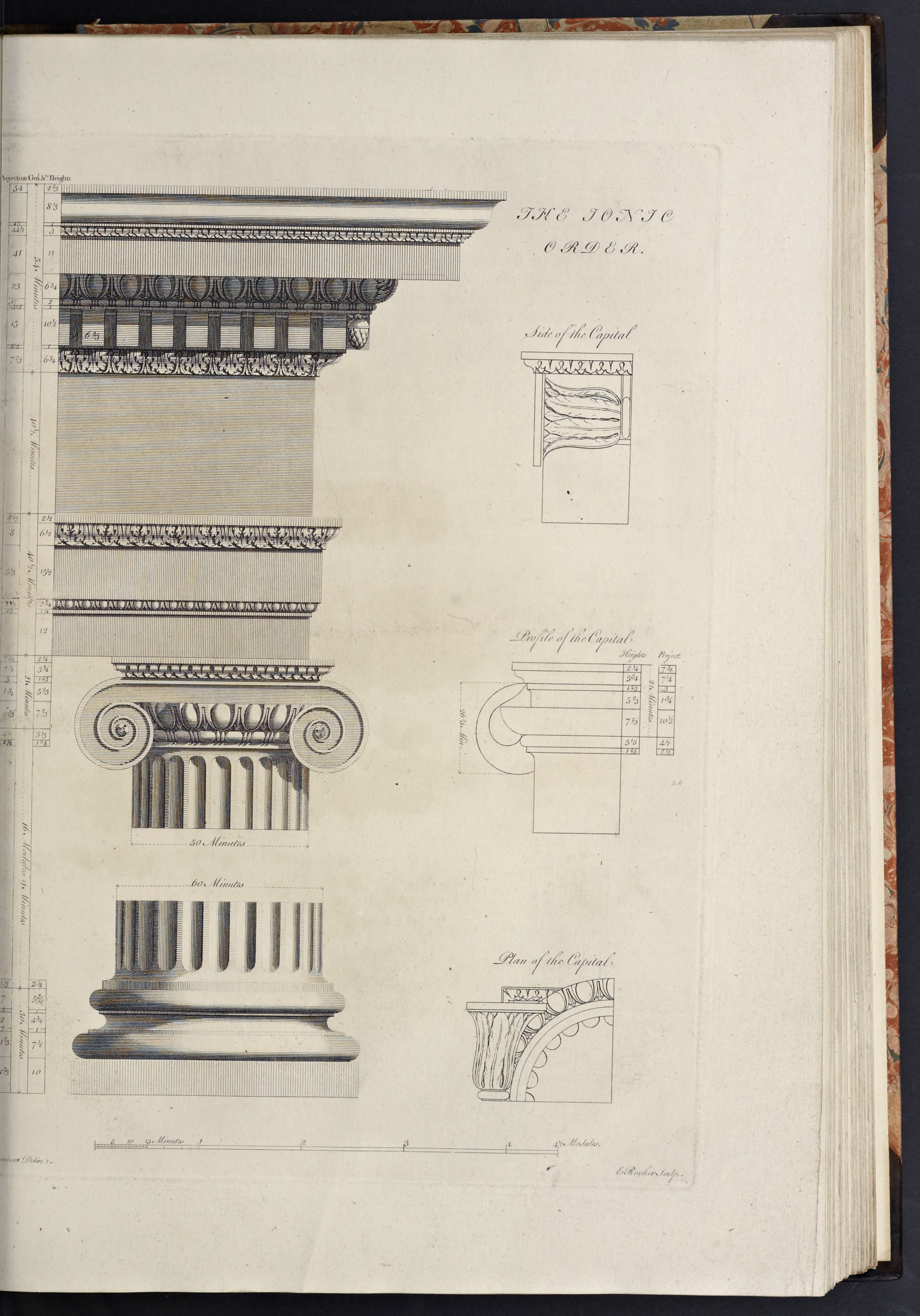
The Ionic Order
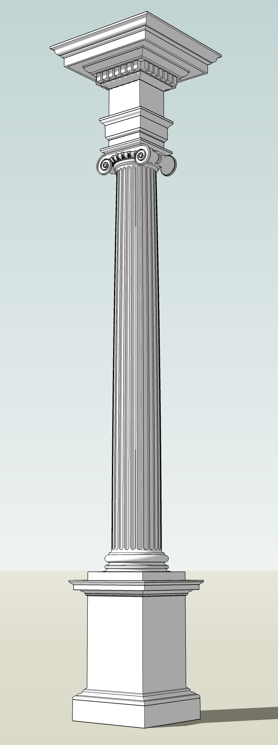
The Ionic order is almost as old as the Doric, and is notable for the prominent volutes, or spirals, in the capital, which are its defining characteristic. It’s column is taller and slimmer than the Doric, and the cornice of its entablature usually features repeating dentils in the cornice, though sometimes they are replaced with simple scrolled modillions.
The basic characteristics of the Ionic order are that:
- The column height ranges from 8 diameters high (per Serlio) to 9 diameters (per Vignola)
- The base is frequently the Attic base, though Vitruvius described a base unique to this order, used by Serlio & Vignola
- The shaft uses it’s own style of fluting, also described by Vitruvius, this being deeper than the Doric and separated by fillets rather than meeting in a point
- The capital features the prominent volutes, separated by bolsters on the sides in the Antique version, and splayed out of the four corners in the Modern or Angular type, in both cases frequently featuring an ovolo with egg-and-dart carving above an astragal with bead-and-reel enrichment
- The entablature usually features an architrave divided into multiple fascias, and a cornice with either dentils, as described by Vitruvius and adopted by Serlio & Vignola, or simple modillion consoles, adopted as standard by Palladio, who also introduced the swelled or pulvinate frieze
The Antique Ionic Order Of Sir William Chambers
Chambers’ Ionic order features a design of the antique profile collected by me [Chambers] from different antiquities at Rome
.
- The column height is 540 min, and the entablature height is 135 min, thus making the order 675 min high.
- The capital (as measured from the top of the astragal to the top of the abacus, disregarding the volutes) is 21 min high and the base is 30 min high, thus making the shaft 489 min high.
- The pedestal is 162 min high, thus making the order with the pedestal 837 min high.
- and, as with all Chambers’ orders, the lower diameter is 60 minutes, and the upper diameter is 50 minutes, making the diminution one-sixth of the column diameter.
Create the Order Profiles
- Start in parallel projection, front view
- Set a guide 30 min to the right of the Centerline (for the lower diameter), and another 11
2/3 min to the right of that (for the projection of the plinth & pedestal die)
The Pedestal Profiles
The Ionic pedestal of Chambers follows the Doric in being a little more elaborate than it’s predecessor, but still being divided and formed in the same way.
- Set a guide 162 min up on the Blue Axis from the Baseline (for the height of the pedestal)
- Set guides horizontally and vertically on the Origin point
- Draw a rectangle from the guides marking the Centerline and top of the pedestal down and out to the guides marking the bottom of the pedestal and projection of the die
- Double-click the face just created, right-click, make component
Pedestal-Die-profile - Set guides, going up from the bottom of the die, for 24 min, 4 min, 1 min, 4 min, 2 min, and 1 min (for the plinth, torus, fillet, cyma reversa, astragal, and fillet)
- Set guides, all going out from the die, for 12 min, 9 min, 8 min, 3
2/3; min, and 2 min (for the plinth & torus, fillet, bottom of the upside-down cyma reversa, astragal & top of the upside-down cyma reversa, and fillet under the top congé) - Draw a line, from the bottom-right corner of the die, out to the last guide on the Red Axis, and then up to the first guide
- Set a guide half the height of the torus inwards from the last projection guide, and draw a line from the last endpoint inwards to the intersection of the new guide with the top of the plinth
- Use the last endpoint as the start point for the bottom of a torus, using the guide above it as the height, then erase the new guide created above
- Draw a line from the top endpoint of the torus, inwards to the next guide, then up to the next guide, then inwards towards the Centerline to the next guide
- From the last endpoint, draw a diagonal line upwards and inwards to the next guide (as a stand-in for the upside-down cyma reversa)
- Draw an astragal above the last line, using the line’s endpoint as the projection, starting by setting a guide half the height of the astragalo inwards to the centerline, and drawing a line to that point, off which the astragal will begin
- Draw a line from the endpoint of the astragal in to the next guide, then up to the next guide
- Draw a congé connecting the last endpoint to the side of the die
- Draw a Line from the top of the congé down to the bottom of the pedestal
- Double-click the face just created and make it a component
Pedestal-Base-Molding-profile - Replace the stand-in diagonal line with an upside-down cyma reversa
- Erase the guides to the right of the die and below the top of the pedestal
- Set a guide, going down on the Blue Axis from the top of the pedestal for 1
2/3 min, 31/3 min, 6 min, 41/3 min, 12/3 min, and 1 min heights (for the crowning fillet, cyma reversa, corona, lower cyma reversa, astragal and fillet) - Set guides, going out on the Red Axis and all from the projection of the Die, for 1 min, 2
1/3 min, 61/3 min, 12 min, 122/3 min, 151/3 min, and 16 min projections (for the fillet, astragal & bottom of the cyma reversa, cyma reversa, corona, cyma reversa, and crowning fillet) - Draw a line, from the top-right corner of the pedestal die, out to the guide marking the greatest projection of the pedestal cap, then down to the next guide, and then in to the next guide (forming the crowning fillet for the cap)
- Draw a diagonal line from the last endpoint downwards and inwards to the next intersecting guides (forming a stand-in for the cyma reversa)
- Draw a line, from the last endpoint, in to the next guide, then down to the next guide, then in to the next guide (forming the corona of the cap)
- Draw a diagonal line from the last endpoint downwards and inwards to the next guide (forming a stand-in for the cyma reversa)
- Draw an astragal following the above guides (and whose projection is equal to the last endpoint)
- Draw a line from the bottom of the astragal in to the next guide, then down to the next guide, then inwards to the next guide, then upwards to the top of the pedestal
- Triple-click the face just created and make it a component
Pedestal-Cap-Molding-profile - Replace the two diagonal lines with cyma reversa moldings
- Erase the guides to the right of the die and below the top of the pedestal
The Pedestal Die Profile
The Pedestal Base Profile
The Ionic pedestal base is formed of a plinth at the bottom, topped by a small torus, over which is a fillet, which supports an upside-down cyma reversa, which has an astragal over it, that is topped by a fillet which merges into the die with a congé.
The Pedestal Cap Profile
The Ionic pedestal cap is formed of a fillet over the die, supporting an astragal under a cyma reversa, which supports the corona, over which is a small cyma reversa molding topped by the crowning fillet.
The Column Base Profiles
Chambers does not use the Ionic Base described by Vitruvius in his famous Treatise (and utilized by both Serlio & Vignola), saying Of the antique base described by Vitruvius, … I think there is no example among the antiques; and being universally esteemed a very imperfect production, I have not even given a design of it.
Instead he uses the Attic Base, which is composed of a Plinth, over which is a large Torus, topped by a Fillet under a Scotia crowned by another Fillet, over which is another Torus somewhat smaller than the lower one. So, as he does not offer an alternative design for this order (as he does for all the others save the Tuscan), I will illustrate the Attec base here.
- Set Guides, going up from the Baseline, for 10, 7
1/2 , 1, 43/4 , 1, and 53/4 min heights (for the Plinth, Lower Torus, Fillet, Scotia, Fillet, and Upper Torus) - Draw a Rectangle, from the Guides marking the Centerline and height of the Plinth downwards and outwards to the Baseline and projection of the plinth
- Double-Click the Face just created and make it a Component
Column-Base-Plinth-profile - Set Guides, going out rightwards from the Lower Diameter, for 4 min, and 7 min projections (for the Upper Fillet, and Upper Torus & Lower Fillet)
- Draw a Torus above the Plinth, going backwards towards the Centerline from the projection of the Plinth
- Draw a Line from the top Endpoint of the Torus, inwards to the next Guide, then up to the next Guide, then inward to the Lower Diameter (forming the Lower Fillet of the Scotia)
- Draw a Line from the last Endpoint up to the next Guide, then outwards to the next Guide, then up to the next Guide (forming the Upper Fillet and space for the Scotia curve)
- Draw a Line from the last Endpoint out rightwards to the next Guide, and use that new Endpoint as the bottom right corner of the Construction Square for drawing a Torus going up to the next Guide
- Draw a Line from the top of the Upper Torus, inwards to the Centerline, then continue it downwards to the top of the Plinth, then outwards to the Lower Torus
- Double-Click the Face just created and make it a Component
Column-Base-Torii-profile - Replace the rectangular stand-in lines between the upper & lower Fillets with a Scotia molding
- Erase any Guides below the top of the Base, and to the right of the Lower Diameter
The Column Base Plinth Profile
The Column Base Torus Profile
The Column Shaft Profile
- Set a Guide 489 min up from the top of the Base (for the height of the Shaft)
- Set a Guide 2
1/2 min up from the bottom of the Shaft (for the Lower Cincture) - Set a Guide 3
1/3 min out from the Lower Diameter (for the Lower Cincture) - Draw a Line, from the Intersection of the Centerline and the top of the Base, out to the Guide marking the Lower Cincture projection, then continue it up to the next Guide
- Draw a Congé, from the last Endpoint, up and in to the Guide marking the Lower Diameter (thus completing the Lower Cincture of the Column)
- Erase the Guides to the right of the Lower Diameter and below the Congé just drawn
- Now go back and draw a Line, from the intersection of the top of the Base and the Centerline, up to the Guide marking the top of the Shaft (forming the Column Centerline)
- Set Guides 3
1/3 and 12/3 min down from the top of the Shaft (for the Astragal and Upper Cincture) - Set a Guide 25 min out from the Centerline (for the Upper Diameter)
- Set Guides 2
1/2 , and 41/2 min out from the Upper Diameter (for the Upper Cincture and Astragal) - Draw a Line from the last Endpoint (at the top of the Shaft Centerline) outwards to the Guide marking the projection of the Astragal, then use the Endpoint of that Line as the start for drawing the Astragal, which you will draw going down to the next Guide
- Draw a Line from the Endpoint of the Astragal in to the next Guide, then down to the next Guide
- Draw a Congé, from the last Endpoint, down and in to the Guide marking the Upper Diameter (thus completing the Upper Cincture)
- Erase the Guides marking the height and projection of the Upper Cincture & Astragal (leaving the Guides marking the Upper & Lower Diameters and top of the Column Shaft)
- Draw a temporary diagonal line connecting the endpoints of the two congé moldings (or connecting the start & stop points for applying entasis, as explained below)
- Double-click the face just created and make it a component
Column-Shaft-profile - Finish by applying entasis to the shaft profile
- Erase any Guides to the right of the Upper Diameter, and below the top of the Shaft
The Column Capital Profiles
The Antique Ionic capital shown by Chambers is of a fairly standard type. It is formed of an ovolo over the astragal of the top of the column shaft, under a channel topped by a fillet, both channel and fillet scrolling out to either side into the volutes which partially hang below the top of the column shaft, with a square abacus on top of the channel, formed only of a cyma reversa and crowning fillet. On the sides of the capital, the volutes are joined together by bolsters that are curved and gathered in the center by a belt form.
The capital shown by Chambers features a rather plain pair of volutes, ornamented only with a small rosette in the eye of the volute, and the channel is completely plain. A peculiarity of this capital is that it lacks the sprigs of honeysuckle ornament that tuck into the junction of the ovolo & volute and are shown by most other authorities, including Serlio, Palladio and Vignola.
Due to the complexity of modeling this capital, we start out the same as for the Tuscan & Doric, creating the baside Profiles, but the majority of the work will be done later, when the capital is being turned into an actual 3D element.
- Set a Guide 21 min up from the top of the Shaft (for the height of the Capital)
- Set Guides, coming down from the Guide just made, for 2
1/4 and 33/4 min heights (for the Fillet & Cyma Reversa of the Abacus) - Set Guides, going out from the Upper Diameter, for 7
3/4 min, 71/4 min, 31/2 min, and 3 min projections (for the Fillet, top & bottom curves of the Cyma Reversa of the Abacus, and the Abacus Core) - Draw a Rectangle, from the intersection of the Guides marking the Centerline and top of the Capital, out to the Guide marking the bottom of the Abacus and the first Guide to the right of the Upper Diameter
- Double-Click the Face just created and make it a Component
Column-Capital-Abacus-Core-profile - From the top right corner of the Component just created draw a Line out to the last Guide on the right, then down to the next Guide, then in to the next Guide, then diagonally downwards and inwards to the next Guide, then inwards to the next Guide, then continue the line upwards to the top of the Capital (thus forming the Abacus Cymatium profile)
- Double-Click the Face just created and make it a Component
Column-Capital-Abacus-Cymatium-profile - Replace the stand-in diagonal line with a Cyma Reversa, and Erase the Guides to the right of the Abacus Core
- Set Guides, coming down from the bottom of the Abacus, for 1
2/3 , and 52/3 min heights (for the Fillet & Channel of the Hollow of the Volute) - Set a Guide 1
3/4 min to the right of the Upper Diameter (for the projection of the Channel of the Hollow of the Volute) - Draw a Line, from the bottom-right corner of the Abacus Core down to the next Guide, then draw a Congé going inwards towards the Centerline to the next Guide
- From the bottom Endpoint of the Conge draw a Line down to the next Guide, then inwards to the next Guide (representing the Upper Diameter), then up to the bottom of the Abacus, then out to the projection of the Abacus Core
- Double-Click the Face just created and make it a Component
Column-Capital-HollowOfTheVolute-profile - Erase the Guides to the right of the Upper Diameter
- Set a Guide 10
1/3 min to the right of the Upper Diameter (for the projection of the Ovolo) - Draw a Line, from the Intersection of the top of the Shaft and the Centerline, up to the next Guide, then out to the Guide marking the projection of the Ovolo, then continue diagonally inwards and downwards to the Midpoint or Center of the top of the Astragal at the top of the Column Shaft, then continue inwards to the Centerline
- Double-Click the Face just created and make it a Component
Column-Capital-Ovolo-profile - Replace the stand-in diagonal line with an Ovolo
- Erase the Guides to the right of the Upper Diameter and between the Abacus & top of the Column Shaft
The Capital Abacus Fascia Profile
The Capital Abacus Cymatium Profile
The Hollow of the Volute Profile
The Capital Ovolo Profile
Creating The Ionic Volute Profile
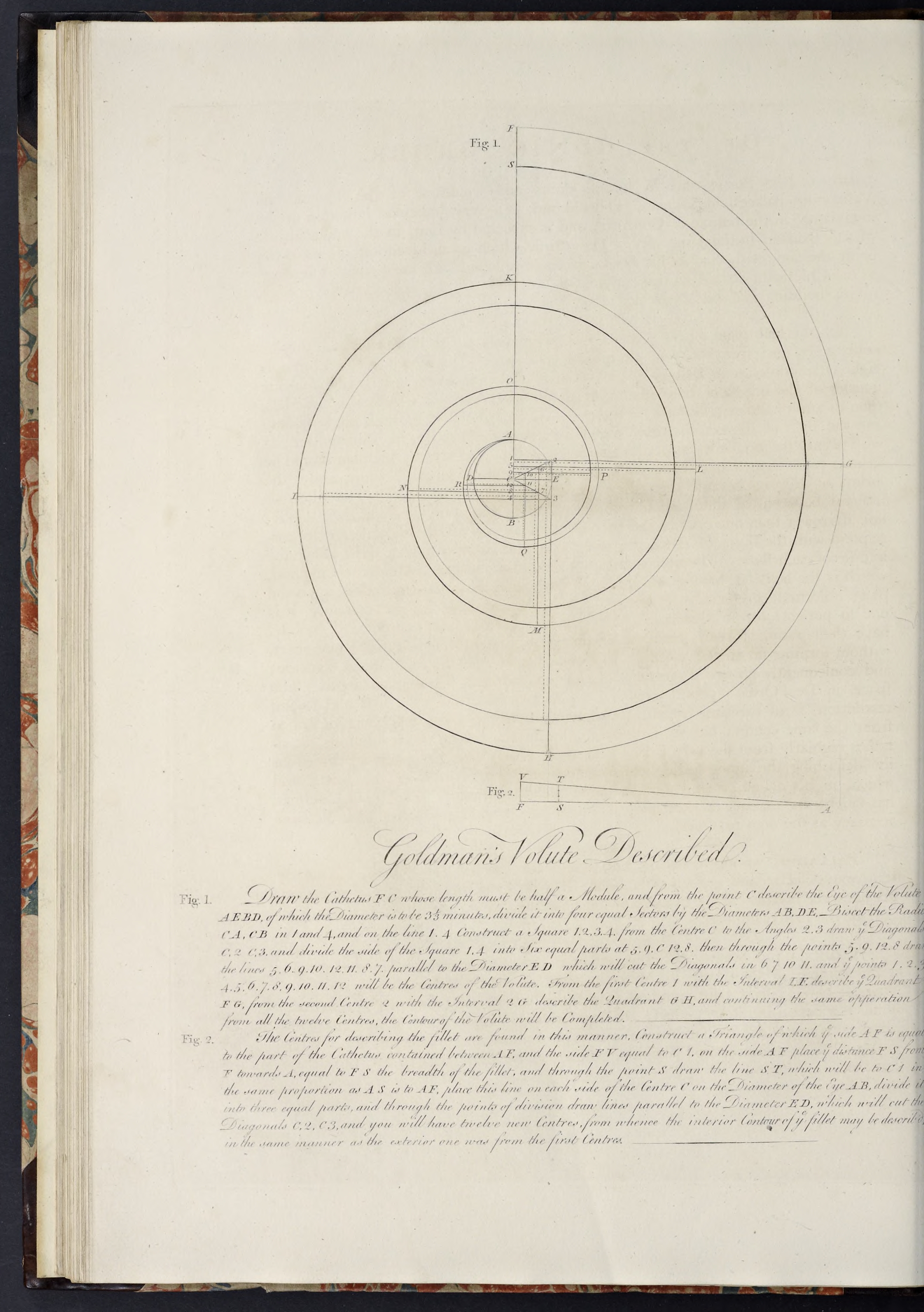
The Ionic Volute is the most defining characteristic of the Ionic Order, and was a source of much thought and theory in the Renaissance, as, while Vitruvius gives a brief description of it in his Treatise, the drawing he refers to that would explain it’s construction was lost. As a result a number of methods were devised to form the volute (as many as twenty-two according to Jeroen Goudeau in his Going Round In Circles. Circumambulate The Vitruvian Volute In Early Modern Architectural Theory), so there is no one, canonical, form of the volute.
In his Treatise William Chambers shows the method devised by by Nicolaus Goldmann in the 17th century, considering it the best
as the circular portions that compose the volute have their radii at their junction, in the same straight line, so that they meet without forming an angle
, and the space between the revolutions diminishes regularly from the very first
.
It is that method that will be used to construct the volute below.
Forming the Volute of Nicolaus Goldmann
This solution first appeared in Goldmann’s work Vitruvii voluta ionica, which was part of the Vitruvian encyclopedia published by Jean de Laet in 1649. In addition to being shown in Chambers work, it was also used by Robert Chitham in his The Classical Orders of Architecture.
The instructions below are based on those found in Chambers treatise, and the designations within the square brackets refer to the diagram illustrating the Ionic volute shown there (and which I have recreated here). You can add the designations to your model using the Text tool if you want, as it might make it easier to follow the steps. The dual indications (appearing separated by a dash) indicate lines from one point to another.
- Start with guides on the column Centerline, the upper diameter, the bottom of the abacus (which will equal the top of the volute), and the top of the column shaft (which determines the length of the catheter and thus center of the eye of the volute); any others can be erased
- Set a guide at the projection of the bottom (or lower curve) of the abacus cymatium (which will determine the distance of the catheter from the Centerline of the column)
- Draw a line to form the catheter, using the guides set above, from the bottom of the abacus [F] down to the top of the astragal [C] (which makes the line [F-C] 15 min)
- Hide all the profile components
- Using the bottom endpoint of the line just drawn [F-C] as the center, draw a circle (using the default 24 sides) with a radius of 1
2/3 min (this forms the construction circle for the eye of the volute); where the top of the circle intersects the line is point [A] - Draw lines from the center of the eye [C] out to the left, right, and bottom edges, dividing the circle into four quadrants (where these lines meet the circle are the points [D], [E], and [B] respectively)
- Divide the lines [C-A] and [C-B] in two, with the divisions forming points [1] and [4] respectively
- Set guides vertically on the right outside edge of the eye of the volute, and horizontally on the two points created above (i.e. [1] and [4])
- Draw a square the height and width of half the eye of the volute, with its left top and bottom at the points [1] and [4] respectively, and its right side equal to the guide just created on the right extremity of the circle (the top and bottom right corners forming the points [2] and [3] respectively)
- Draw a pair of lines from the center [C] diagonally out to the two right corners of the square [2] and [3], forming lines [C-2] and [C-3]
- Select all of the geometry created so far (including the text labels if you added them) and make it a component
Volute-Eye-construction - Open the component just created and copy the vertical lines [1-C] & [4-C], and the entirety of the diagonal lines [C-2], and [C-3], then close & hide the component, and Paste-in-Place
- Divide the lines [C-1] and [C-4] into 3 parts each; the upper two divisions becoming points [5] and [9], while the lower two divisions become points [12] and [8] (respectively coming down in order from the top)
- From the four points just created, draw lines going out to the right on the Red Axis till they intersect the two diagonal lines: point [5] will go out to form point [6]; point [9] will go out to form point [10]; point [12] will go out to form point [11]; and point [8] will go out to form point [7]
- Select all of the geometry just created (including the text labels if you added them) and make it a component
Volute-Arcs-Outer-construction - Draw a quarter-circle arc, centered at point [1] and with a radius set to point [F] (aka the bottom of the abacus), outward to the right; the endpoint of the arc will become point [G]
- Continue to draw quarter-circle arcs, centered at points [2], [3], [4], [5], [6], [7], [8], [9], [10], [11], and [12], their endpoints forming the Startpoints for the next arc (becoming points [H], [I], [K], [L], [M], [N], [O], [P], [Q], [R] respectively)
- Select all of the arcs created and make them a component
Volute-Arcs-Outer - Hide both the Volute
Arcs-Outer andArcs-Outer-construction components, and unhide theVolute-Eye-construction component - Open the component
Volute-Eye-construction and copy lines [F-A] and [A-1], close & hide the component, and Paste-in-Place - Select the shorter line and rotate it 90 degrees clockwise from where it joins the longer line (this shorter line becomes line [V-F] with the longer line being [F-A])
- Draw a line connecting points [V] and [A] to close the triangle
- The height of the fillet of the volute is 1
2/3 min, so set a pair of guides using that distance: one coming down from the guide marking the bottom of the abacus, and the second going up from line [V-F] (the bottom of the triangle) towards point [A] - Draw a line [S-T]connecting lines [F-A] and [V-A] along the guide just set coming up from line [V-F], then erase that guide
- Copy line [S-T] into memory, triple-click the face of the triangle, make component
Volute-Arcs-Inner-scale , then hide it, and Paste-in-Place - Unhide the
Volute-Eye-construction , rotate the short line 90 degrees clockwise so it is vertical on the Catheter line, then move it down so its bottom endpoint is on the center of the eye at point [C], then move/copy the line down from endpoint to endpoint, so you have two lines flanking point [C] that are a little shorter than the lines [C-1] and [C-4] - Open the component
Ionic-Volute-Goldmann-construction and copy lines [C-2], and [C-3], close and hide the component, and Paste-in-Place - Divide the two short vertical lines into 3 parts each and draw lines going out to the right on the Red Axis toward the diagonal lines, from each of the 3 divisions above and below [C] (including the very top and bottom)
- Select all of the geometry just created (including the text labels if you added them) and make them a component
Volute-Arcs-Inner-construction - Using the same method as above, create the series of quarter-circle arcs, using the new centers, and with the radius of the first arc being the guide marking the bottom of the fillet of the volute (instead of the bottom of the abacus)
- Once all the arcs have been created, select all of them and make them a component
Volute-Arcs-Inner - Hide all the components, except for the Volute
Arcs-Outer &Arcs-Inner components - Select the two components, copy them into memory, hide the originals, and Paste-in-Place
- With the components selected, make a new component
Column-Capital-Volute-Fillet-profile , then open it, and explode the arc components - Using the Weld extension, carefully join the innermost exploded arcs back together into a pair of arcs joining together at the end into a single arc that completes the volute where it will meet with the eye of the volute, and afterward select each of these larger arcs in turn, weld them to the separate arcs they are connected to until you have 3 arcs in total: the Outer Arc, the Inner Arc, and the small innermost Arc where the other two join together.
- Draw a line from the top of the outer volute
1/2 min inwards on the Red Axis (this will be to the projection of the abacus core), then down on the Blue Axis to the height of the endpoint of the inner arc, then outwards on the Red Axis to the endpoint of the inner arc, then add each small added segment to it’s attached arc with the Weld extension (thus forming a face for the volute fillet), then close the component - Unhide the
Volute-Eye-construction component, copy it into memory, hide the original, Paste-in-Place, right-click, Make Unique, and renameColumn-Capital-Volute-Eye-profile - Open the new component and erase all the lines, leaving only the circle
- Hide all the components (except for the
Abacus-Core-profile ) and erase all the guides (except for the Centerline and upper diameter)
The Catheter and Eye of the Volute
Create The Outer Arcs
Create The Inner Arcs
To create the centers for the inner arcs (which form the fillet of the volute) you need to create a secondary proportioning element, which will be used to create the divided line that will be used instead of lines [1-C] and [4-C].
Create The Volute Fillet
Create the Eye of the Volute
The Entablature Profiles
With the Ionic Entablature Chambers returns to the standard practice of dividing the height of the Entablature into 10 parts, and giving 3 each to the Architrave & Frieze, and the remaining 4 to the Cornice.
- Set Guides, starting from the top of the Capital and going up on the Blue Axis, for 40
1/2 min, 401/2 min, and 54 min (for the tops of the Architrave, Frieze, and Cornice) - Draw a Rectangle, from the Guides marking the Centerline and top of the Cornice downwards to the Guides marking the top of the Capital and the Upper Diameter
- Double-Click the Face just created and make it a Component
Entablature-Frieze-Core-profile - Set Guides, going up from the top of the Capital, for 12, 1
1/4 , 23/4 , 151/2 , and 61/2 min heights (for the Lower Fascia, Fillet, Ovolo, Upper Fascia, and Cyma Reversa, the crowning Fillet occupying the remaining space up to the Frieze) - Set Guides, all going out from the Upper Diameter, for
2/3 , 22/3 , 31/3 , 4, 8, and 82/3 min projections (for the Fillet over the Lower Fascia, the Ovolo, Upper Fascia, Cyma Reversa beginning & ending, and crowning Fillet) - Draw a Line, from the Guides marking the Upper Diameter and the first Guide above the top of the Capital, out to the next Guide, then up to the next Guide, then continue the Line diagonally upwards and outwards to the next Guide, then out to the next Guide (this forms the Fillets and stand-in for the Ovolo between the two Fascias)
- From the last Endpoint, continue the Line upwards to the next Guide, then out to the next Guide, then continue the Line diagonally upwards and outwards to the next Guide, then out to the next Guide (this forms the Upper Fascia and the stand-in for the Cyma Reversa)
- From the last Endpoint, continue the Line then up to the next Guide, then backwards to the Upper Diameter and then down to the Guide marking the height of the Lower Fascia (this forms the crowning Fillet of the Architrave)
- Double-Click the Face just created and make it a Component
Entablature-Architrave-Molding-profile - Replace the lower diagonal line with an Ovolo, and the upper diagonal line with a Cyma Reversa
- Erase the Guides below the top of the Architrave and to the right of the Upper Diameter
- Set Guides, going up from the Guide marking the bottom of the Cornice, for 6
3/4 , 111/2 , 1, 2, 63/4 , 11, 3, 1, and 81/3 , min heights (for the Cyma Reversa, Dentil Fascia, Fillet, Astragal, Ovolo, Corona, Cyma Reversa, Fillet, and Cyma Recta, the crowning Fillet occupying the remainder) - Set Guides, going out from the Upper Diameter, for
2/3 , 72/3 , 81/3 , 152/3 , 17, 23, 41, 411/2 , 441/2 , 45, and 54 min projections (for the Cyma Reversa reveal & curve, the Dentil Fascia, Fillet, Astragal, Ovolo, Corona, Cyma Reversa reveal & curve, Fillet, and Fillet over the Cyma Recta) - Draw a Line, from the Guides marking the Upper Diameter and height of the Frieze, out to the next Guide, then continue it diagonally upwards and outwards to the next Guide, then out to the next Guide (this forms the Cyma Reversa stand-in)
- Continue the Line up to the next Guide, then out to the next Guide, then up to the next Guide (this forms the Dentil Fascia)
- Draw an Astragal the height specified by the Guides created above, and coming back from the specified projection
- Draw a Line, from the top Endpoint of the Astragal, diagonally upwards and outwards to the Guides marking the height and projection of the Ovolo, then out to the next Guide
- Draw a Line, from the last Endpoint, up to the next Guide, then out to the next Guide, then diagonally upwards to the Guide Intersection, then out to the next Guide, then up to the next Guide (this forms the Corona and Cyma Reversa with it’s Fillet above it)
- Draw a Line, from the last Endpoint, diagonally upwards and outwards to the next Guide, then up to the next Guide, then inwards to the Guide marking the Upper Diameter, then back down to the Guide marking the bottom of the Cornice
- Double-Click the Face just Created and make it a Component
Entablature-Cornice-Molding-profile - Replace the lowest diagonal line with a Cyma Reversa, the next one up with an Ovolo, the next one up with another Cyma Reversa, and the last one with a Cyma Recta
- Set a Guide 2 min up from the bottom of the Corona
- Set a Guide 1
1/2 min to the right of the Guide marking the projection of the Ovolo, and another Guide 31/2 min in from the projection of the Corona - Draw a Congé, from the intersection of the right Guide just set and the bottom of the Corona, upwards and inwards to the Guide marking the top of the Drip Mold
- From the last Endpoint, draw a Line inwards to the next Guide, then down to the bottom of the Corona
- Select the Geometry just created, Cut/Copy it into memory, Open the Cornice Component, Paste-in-Place, Erase the line at the bottom of the Drip Molding, then Close the Component
- Erase all the Guides
The Entablature Frieze Profile
The Architrave Profile
Chambers’ Ionic Architrave is formed of a Lower Fascia, topped by a Fillet under an Ovolo, which supports the Upper Fascia, which is crowned by a Cyma Reversa under a Fillet.
The Cornice Profile
Chambers’ Ionic Cornice is composed of a Cyma Reversa supporting a Dentil Fascia, which is topped by a Fillet and Astragal, over which is an Ovolo supporting the Corona, which is under a Cyma Reversa & Fillet, which support a Cyma Recta and crowning Fillet.
The Dentil Profile & Repeating Element
The Dentils are 10
The Dentil can be created as a Rectangle 6
The Dentil projects out the same amount as it’s width, so Copy the Dentil Profile, Make Unique, rename
The Entablature Soffit Profile
Chambers does not advocate embellishing the Soffit of the Ionic Entablature, except for a Drip Molding, following Vignola’s example.
In his Plate he depicts it as dashed lines without any dimensions, just like in the Tuscan Plate, so the below is extrapolated from his drawing.
Form the 3D Elements
Just as with the Doric Order, additional elements are needed for forming the full elements of this order, so as the profiles are turned into 3D shapes, the additional elements will be created as needed.
The Standalone Pedestal
- Hide all the components except those for the pedestal profiles
- Copy the three pedestal components into memory, hide the originals, Paste-in-Place the copies, Right-click on the components, Make Unique, and rename
- Open the
Pedestal-Die-standalone , and turn it into a square component, then close the component - Now wrap the cap & base moldings around the die core
- Select all three pedestal components and make a standalone component
Pedestal-standalone
The standalone pedestal is formed by wrapping the molding components around the central core component.
The Pedestal Die
The Pedestal Cap & Base Moldings
The Pedestal
The Column Base Plinth
- Unhide the Base Plinth Profile Component, Copy it into memory, Hide the original, Paste-in-Place, Right-Click, Make Unique, and Rename
Column-Base-Plinth - Open the component, and Push/Pull the face forward, sideways and backwards an amount equal to it’s width (as it is a perfect square)
- Hide the Base Plinth Component
The Cylindrical Components of the Column
Creating a plain, unfluted Ionic Column Shaft, along with the Base Torus & Capital Ovolo, can be done following the same steps as for the Tuscan & Doric Columns, only changing the number of wedges created from 20 to 24.
- Unhide the Profiles, Select all three, Copy into memory, Hide the originals, Paste-in-Place, and rename (I replace “profile” with “wedge”)
- Turn each of the copied components into a wedge-based cylinder by creating 24 wedges of 15 degrees each, which are then Rotated & Copied to form the cylinder
- Hide the three cylindrical Components just created
The Column Capital Abacus
As the Abacus of the Antique Capital is square in plan, it can be created the same way as for the Doric Abacus, using Push/Pull on the Core, and wrapping the Molding around it with Follow-Me.
- Unhide the
Column-Capital-Abacus-Fascia-Core-profile component, copy it into memory, hide the original, Paste-in-Place, Right-click, Make Unique, and renameColumn-Capital-Abacus-Fascia-Core - Unhide the
Column-Capital-Abacus-Cymatium-Molding-profile component, copy it into memory, hide the original, Paste-in-Place, Right-click, Make Unique, and renameColumn-Capital-Abacus-Cymatium-Molding
The Column Capital Abacus Fascia
The Column Capital Abacus Cymatium
The Column Capital Volutes
The Ionic Volute is formed of the Fillet (whose front face diminishes in width as it goes deeper into the spiral of the Volute), the Hollow of the Volute (a channel stretching between the two Volutes on each side and penetrating into the spiral of each Volute between the curves of the Fillet), and the Eye of the Volute (a circle at the center of the Volute spiral).
The Fillet & Hollow of the Volute are shown by Chambers in his Profile of the Capital as being connected by a Congé at the top, and (apparently) with a straight bottom, which appears common to many Authorities. The problem in creating them in SketchUp is that the width (on the Front View) of both the Fillet and Hollow both, are reduced as the Volute turns in upon itself, so you cannot use the Follow-Me Tool on the Hollow of the Volute Profile and therefore must find another method. The method that I use is to rotate the Hollow profile around the Volute, scaling it down as the channel narrows, then using the arcs from the Volute and Hollow to form curved surfaces using the Curviloft Extension.
- To start it is advised to Hide all the other Geometry
- Unhide the Volute Eye profile, Copy it, Hide the original, Paste-in-Place, Make Unique and Rename
Column-Capital-Volute-Eye - Open the Component just created and use Push/Pull to extrude the Face backwards 1
1/4 min, then Close the Component - Un-Hide the Volute Fillet Profile and the Hollow of the Volute Profile Components, make Copies, Hide the originals, and Make Unique
- Rotate the Hollow Profile copy 90 degrees clockwise towards the back, using it’s right top corner as the rotation point (this will form the beginning of both the Channel across the front of the Capital and the Channel the flows into the curve of the Volute)
- Move/Copy the Hollow Profile, using the bottom corner of the ‘Fillet’ part of the profile as the ‘Selection Point’, from the bottom of the top of the Volute down (following the inner side of the curve of the Volute) till it reaches about the middle of the right side of the Volute
- Move/Copy the last Hollow Profile, using the same selection point and again following the inner side of the curve, down to the middle of the bottom of the Volute, then Move/Copy that profile upwards to the left in the same manner till it reaches the left side of the Volute, and repeat this pattern until you have moved/copied 10 Hollow Profiles (not including the first one) around the inner curve of the Volute as it reaches the Eye
- Now go back to the 2nd Hollow Profile, on the right side of the outer curve of the Volute, and Rotate it 90 degrees clockwise (swinging it up from the bottom, with the ‘Selection Point’ that links it to the Volute as the Center), then repeat for all of the rest of the profiles, rotating them so their Selection Points remain in position and the longer sections all point towards the inside of the Volute
- Open the Volute Fillet Profile copy, and use the Push/Pull Tool to extrude the Face backwards 1
1/4 min (which will make it the depth of the Hollow of the Volute) - Double-Click the back Face of the Volute, Copy it into memory, Close & Hide the Component, Paste-in-Place, and make a Group
- Open the Eye of the Volute Component, Double-Click the back Face, Copy it into memory, Close & Hide the Component, Open the Group just created, and Paste-in-Place, then Close the Group
- Select the first Hollow Profile copy, at the top of the Volute, Open it, Erase it’s bottom, back, top, and closest front (or Fillet) Edges, so all you are left with is the curve at the top and the line connecting to it at the bottom, then Close the Component
- Explode this Component, draw a temporary Line from the bottom Endpoint out a little on to the left or right, Select it, and Move it upwards exactly on the Blue Axis, till the Endpoint connected to the exploded profile is even with the top of the Volute curve right above it (not the very top of the Volute, just the top of the closest curve to the bottom of the profile), then Erase the temporary line
- With the next Hollow Profile on the right, Select it, and use the Scale Tool to reduce it’s length so it fits between the Volutes it stretches across, using the Scale Grip closest to the center of the Volute, and scaling it outward only from that direction (so the curved endpoint does not change position), then repeat this for all the other profiles (the last three being scaled to the edge of the Eye instead of the Volute)
- Explode the Group containing the Volute & Eye, and Erase the small line connecting the two arcs together at the top (to remove the Face)
- Explode each of the Hollow of the Volute Components and go through and extend any long lines forming the diminishing Hollow of the Volute till they reach the Volute arcs (and as you correct the connections Select the lines & arc forming each Hollow Profile grouping and use the Weld Extension to join them into one piece)
- Select the inner arc of the Volute and Move/Copy it 1
1/4 min frontwards on the Green Axis, then Erase the original inner arc - As the inner Endpoint of the Volute arc does not meet with the actual Eye of the Volute, draw a short Line connecting the outer arc with the Edge of the Eye of the Volute, then Move/Copy that Line frontwards 1
1/4 minutes and join it to the Copied inner arc Endpoint, and then draw a Line connecting the two Endpoints along the Green Axis - Erase the outer arc of the Volute at it’s greatest diameter, where the Endpoint is located at the very top of the Volute unconnected to anything.
- Triple-Click the Geometry just created and make it a Component
Column-Capital-Volute-Hollow-construction , then Copy it into memory, Hide it, Paste-in-Place, and Explode - Starting at the top, Select the four arcs making up the 1st and 2nd Hollow profiles and the 1st and 2nd inner and outer arc segments, then activate the Curviloft Extension and choose ‘Skinning of Shapes - Loft Junction following Two Paths’
- After the Extension has created a new Group with the curved surface, Hide the Group, and continue on around the Volute, till you come to the 8th area (where the inner and outer arcs join to the Eye of the Volute), as for this area, you will need to be careful to Select the two Hollow arcs and the inner and outer arcs, but also the additional arcs at the bottom connecting the outer arc to the Eye and the edge of the Eye itself
- From this point forward, continue as before, but instead of the inner arc of the Volute you will Select the arc forming part of the Eye of the Volute
- When you get to the very last section, you will need to cleanup first in order to get a correct surface, so start by deleting the arc of the Eye coming off the very top end of this area, then the pieces of the inner arc coming off the top left of the straight ending line, and any others that connect with it; in short, all you want is the straight line coming out frontwards towards the top of the Eye of the Volute, the arcs connecting to that forming the left side of the Eye, the Hollow arc coming out from those arcs towards the bottom of the Eye, and the arc connecting that Hollow arc with the straight line at top
- With the last surface created, Uh-Hide the Groups containing the surfaces that will form the Hollow of the Volute, Select all the Groups & Geometry, make them a Component
Column-Capital-Volute-Hollow - Open the new Component, Explode all the Groups inside, Erase the Face of the Eye, and Orient the Faces correctly if needed, then Close the Component
- Un-Hide the Volute Fillet Profile Copy created earlier, Open it, and use Push/Pull to extrude the back 1 min further backwards on the Green Axis (making for a total depth/width of 2
1/4 min for the depth/width of the Volute Fillet when looked at from the side), then Close & RenameColumn-Capital-Volute-Fillet - Un-Hide the Hollow of the Volute Profile Component, Copy it into memory, Hide the original, Paste-in-Place, Make Unique, and rename appropriately
Column-Capital-HollowOfTheVolute-channel - Rotate the Component 90 degrees clockwise (just like was done earlier with the earlier Copy), then Open it, use Weld to join the arc and line at the front, and use the Push/Pull Tool to extend the Face inwards towards the Centerline of the Column for 56 min
- Unhide the Eye of the Volute Component
The Eye of the Volute
The Hollow of the Volute
If you cannot scale them perfectly to meet the Volute (which can happen, as it is difficult), get as close as you can then go back when all the scaling is done and add extra Lines to make the connections.
Also, you can Triple-Click the long line and see whether the Volute arc is selected as well, since it if it, then the long line connects.
The Fillet of the Volute
The Channel of the Capital
It is useful at this point to select the four Components created (the Eye, Fillet, Hollow & Channel) and make them a Group, then Un-Hide the Abacus Core Component, and Move the Group just created frontwards till the front of the Fillet is even with the front of the Abacus Core, then Hide the Component & Group
The Column Capital Bolsters
As stated earlier, I postponed creating the Bolster elements as they are easier to create along with their 3D forms, which we are ready to do now.
The below instructions are based principally on William Chambers’ example in his Treatise, augmented by information gleaned from other sources to better understand how I could form the shapes in SketchUp. Where there are differences between either Chambers’ design and other Authorities, or between Chambers’ design and my interpretation, I will do my best to point out and explain what those differences are and, in the case of my interpretations, why they were done.
As stated in the text, the Ionic Bolster stretches between the front and back Volute on either side of the Ionic Capital, with a Belt wrapped around it’s middle, usually connecting it to the Abacus above it. They can appear as various shapes depending on which Authority you follow, and have been variously described as representing the rolled bark of a tree or a woman’s coiled hair.
In my research I have found four basic methods of how they are shaped and connect to the Abacus:
- In many Greek buildings, and in the exemplar Orders of both Serlio and Palladio, the Bolster is a single flattened C-shape curving from front to back on their bottom and outside profiles, with the top profile curving up and merging into the bottom of the Abacus (either completely or into a narrow vertical strip that the flattened curve comes up against and which allows the projection of the Belt to meet the underside of the Abacus horizontally instead of vertically).
- At the Temple of Fortuna Virilis in Rome the Bolsters have a shallow S-shape on their bottom and outside profiles flanking the central Belt, with the top profile being the same form and curving up and merging into the bottom of the Abacus like those of Serlio & Palladio.
- In some Greek examples (such as the Temple of Apollo at Dydymus, the Temple of Minerva Polias at Priene or the Aqueduct of Hadrian in Athens, which can be seen in The Greek & Roman Orders by J. M. Mauch) as well as Roman examples (like those of the Basilica Ulpia in Rome and an Ancient Capital in Santa Maria in Trastevere in Rome, shown in Greek and Roman Architecture in Classic Drawings by Hector d’Espouy) the Bolster is again a single flattened C-shape curving from front to back, but here it is not only on their bottom and outside profiles, but also their top profiles, the latter going (relatively) straight back into a simple vertical plane coming down from the bottom of the Abacus.
- The forms shown by Vignola, Perrault & Chambers are more confusing. All three show the Bolster with an S-Curve along the bottom, outside and top profiles, which would imply the Bolsters go straight back into a vertical plane. However, they also show a Belt going up to the Abacus. In Vignola’s case the Belt clearly has a ‘top’ shown for the Fillets & central section of the Belt, at the approximate height of the Ovolo. Perrault’s illustration clearly does not have a top to the Belt and shows it continuing unbroken to the underside of the Abacus. While Chambers’ drawing has a top to the Astragal, but is missing the top lines for the Fillets of his Belt. Also, the profiles of all three Authorities clearly show only a single sectional profile for the Bolster & Belt that shows the curve going from the outer profile up to the underside of the Abacus.
How these last Bolsters are supposed to appear is therefore something of a mystery to me. They could have the Bolster going straight back and the profile only referring to the Belt (though they don’t show a separate profile for the Bolster and Vignola & Chambers show tops for the Belt). Or they could have the Bolster and Belt going straight back with the Belt going straight up to the Abacus along the vertical plane (though that would not account for the profile nor for Perrault’s continuous Belt). The last possibility is that the Bolster & Belt have the same profile for their bottom, outside & top profiles, but that the top profile merges into a curve that flows up to the bottom of the Abacus, with the top profiles on the side views and the lack of ornament above it merely stressing the curve at that point which then flattens as it gets closer to the Abacus.
Due to the supposed nature of the Bolster as a softer material draped over the column and held down by the Abacus I am going to go with the last possibility and show the Bolster profile curve up into the bottom of the Abacus. I want to stress, however, that this is only my interpretation, and should not be taken as any kind of statement of fact or claim to Authority. If you would like to form the Bolster differently, please do so, the following steps can be adjusted for several different looks with a little adjustment.
- With all the Geometry hidden except for the Profiles of the Capital Abacus Cymatium & Core, and looking at them from the Front View
- Set Guides
3/8 min and 1 min down from the bottom of the Abacus Core Profile (for the heights of the Fillets & Astragals - Set Guides
3/8 min, 2 min, and3/8 min, back from the outer edge of the Abacus Core Profile heading in towards the Centerline (sequentially, not from the same point, for1/2 the center Fillet, the Astragal, and the side Fillet) - Draw a Line from the right bottom corner of the Abacus Core, down to the first Guide, then inwards to the next Guide
- Draw a half-circle Arc with it’s curve pointing downwards, starting from the last Endpoint and ending on the next Guide towards the Centerline, with the Radius being 1 min (or equal to the Guide just below it)
- Draw a Line from the left Endpoint of the Arc leftwards to the next Guide, then up to the bottom of the Abacus, then back rightwards to the beginning point of the very first line
- Double-Click the Face just created and make it a Component
Bolster-Belt-half-profile - Hide the Belt Half Component, and Erase the Guides
- With the Column Shaft, Capital Ovolo and Abacus Core & Cymatium, Profiles visible, and using Front View
- Set horizontal Guides at the heights of the top of the Ovolo and bottom of the Astragal, as well as a vertical Guide at the projection of the Abacus Core
- Some distance to the right of the existing Profiles, draw a Square between the two horizontal Guides created above
- Set a pair of Guides diagonally from corner to corner of the Square to get the center-point, and draw a Circle whose Radius is out to the sides of the Square (which should be 5
1/2 min, and will be the greatest projection of the Bolster after the scaling done below) - Now draw another Circle, using the same center, but with a radius of 4
1/8 min (this being 13/8 min less than the larger circle, and thus equal to the depth of the Belt, and will be the smallest projection of the Bolster after scaling) - Triple-Click the Geometry and make it a Component
Bolster-inner-section-profile , then Erase the diagonal Guides - Move the Component over towards the Centerline till it’s left edge is even with the projection of the Abacus Core
- Select the Component, activate the Scale Tool, and click the ‘Grip’ in the middle of the left side of the Component and move it rightwards slightly to start ‘Red Scale about Opposite Point’, then type 0.975
- Then do the same with the Grip on the right side of the Component moving leftwards, using the same amount (0.975)
- Finally, click the Grip in the middle of the top of the Component, and move it upwards slightly, then type 1.15
- Now, Open the Component and Erase the straight lines that formed the original square, along with the larger circle (oval) that is no longer needed, and Close the Component
- Un-Hide the Belt Half-Profile Component, Copy it into memory, Close & Hide the original, Paste-in-Place, Right-Click, Make Unique
- Open the Inner Section Profile, and draw an Arc, starting from the bottom outer corner of the Abacus Core and going down to just right of the top of the oval (this will be the shape of the Belt & Bolster as they swoop upwards to the Abacus)
- Draw a Line, going from the midpoint of the left side of the oval (that closest to the Centerline) up to the top of the Ovolo, then Erase the arc to its right (this will form the backside of the Bolster coming in from the Volute), and Close the Component
- Move/Copy the Belt Profile Copy downwards on the Blue Axis till it’s top is even with the top of the Ovolo, then Rotate it 90 degrees counter-clockwise frontwards (keeping it’s right corner aligned with the Ovolo Profile), then Rotate it another 90 degrees, this time clockwise towards the Centerline, with the straight top Edge being the pivot, so that the bulge of the Arc points towards the Centerline
- Now move it over to the right on the Red Axis till it’s rear right corner meets the Endpoint on the vertical line of the Inner Section Profile
- Right-Click the Component and Make Unique
- Open the Inner Section Profile Component, Select the vertical Line and the Arc from the original Circle (not the Arc going up to the Abacus), Copy them into memory, Close & Hide the Component, Open the Belt Profile Copy you just Moved, Paste-in-Place and use the Weld Extension to join the Pasted Line & Arc together
- Select the joined Arc, activate the Follow-Me Tool, and click on the Belt Profile Face
- Double-Click on the Belt Profile Face at the top of the right outer end of the Component (the one at a diagonal angle), Copy it into memory, Close & Hide the Component, and Paste-in-Place (this will form the bottom of the Belt that will connect up to the Abacus)
- Rotate the first original Belt Half-Profile Copy 90 degrees counter-clockwise frontwards and then 90 degrees counter-clockwise upwards to the right, using the bottom right corner of the Abacus Core as the pivot point, so the bulge of the curve points out away from the Centerline
- Use the Scale Tool on the Belt Half-Profile Component, selecting the Grip on the right Midpoint (at the top of the half-circle), and moving it leftwards till it is even (or slightly behind) the projection of the bottom curve of the Abacus Cymatium Profile
- Unhide the Inner Section Profile, Open it, Select the Arc going up to the Abacus, Copy it into memory, Close & Hide the Component, and Paste-in-Place
- Draw another Arc, starting from the rear top right endpoint of the Belt Half-Profile Component you just scaled (which will be the top of the central half Fillet when finished) and finishing at the corresponding point on the diagonal Belt Half Profile you pasted earlier
- Once the Arc is drawn, Move/Copy it from the Endpoint of the top of that Fillet out frontwards till it is at the intersection with the half-circle
- Select all three Arcs coming down from the Abacus, and Move/Copy them out some distance frontwards on the Green Axis, then Right-Click and Flip Along Green Direction, and Move them rearwards till they are attached to the Belt Profile Face in the appropriate location
- Triple-Click on the diagonal Belt Profile Face to select it and all six Arcs going up to the Abacus, Cut/Copy them into memory, open the remaining Belt Profile Component, and Paste-in-Place
- Select All of the Geometry in the Opened Component, and Activate the Curviloft Extension ‘Skinning of Shapes, Loft junctions following two paths’, which should create a Group with surfaces between all the lines and arcs that were selected
- Close that Component, then Un-Hide the other Belt Half Profile Copy, Select both, and create a new Component
Column-Capital-Bolster-Belt-half - Open the new Component, Explode the two inner Components, along with the Group that Curviloft created, then Close and Hide the new Component
- Erase all the Guides
The Bolster Fillet
The Bolster Fillet is a small Fillet that separates the Volute Fillet from the Bolster in Chambers & Palladio’s designs. This also forms the greatest diameter for the Bolster, around which will be placed the profiles that will create the shape of the Bolster when seen from the side.
- Un-Hide the Group containing the Volute Components, Open the Group, then the Volute Fillet Component, and Double-Click the back Face, Copy it into memory, Close the Component, then the Group, and Hide the Group, and Paste-in-Place
- Double-Click the Geometry and make it a Component
Column-Capital-Bolster-Fillet - Open the Component and Erase the Inner Arc and the straight line coming down from the top Endpoint of the Outer Arc
- Select the Outer Arc and activate the Offset Tool, and offset the Arc
3/4 min inwards towards the center of the spiral, then Erase the Outer Arc - Draw a Line from the top Endpoint of the remaining arc down till it reaches it’s own curve to form a Face, then Erase any remaining arc segments in the inside area of the Face
- Use the Push/Pull Tool to extrude the Face backwards
3/4 min, then Double-Click the new back Face, Copy it into memory, and Close & Hide the Component - Paste-in-Place the copied Face, Double-Click and make it a Component
Bolster-Profile-outer), then Open it, Erase the short vertical line, and Close it (this will create the Outer Profile to use when placing the Bolster S-curve profiles in the next step) - Unhide the Inner Section Profile, Move/Copy it 2
3/4 min frontwards on the Green Axis, then Right-Click and Make Unique, RenameBolster-Profile-inner , and Hide the original Component - The first profile will be that of the uppermost top where it meets the bottom of the Abacus, so draw a Line from the top of the Inner Profile Copy, frontwards on the Green Axis, till it is even with the Endpoint of the Bolster Fillet Group (which I will refer to from now on as the ‘Outer Profile Group’), then Continue it downwards on the Blue Axis till it reaches the top of the Endpoint of the Outer Profile Group, then draw a Circle centered on the bottom Endpoint of the short Line with a Radius going up to it’s top, and use that as a plane to draw an Arc connecting the Endpoint of the long line coming out on the Green Axis with the curved arc of the Outer Profile (so you don’t have a right angle here), then Delete the short line on the Blue Axis
- Select the Line and Arc just drawn, make them a Component
Bolster-Profile-under-abacus , then Open the Component, use Weld to join the exploded Arc back into one piece, and Close the Component - Triple-Click the Circle drawn above, Cut/Copy it into memory, Open the Outer Profile Component, Paste-in-Place, then Erase the part of the profile curve extending into the circle, then Erase the circle itself, and Close the Component
- The next Profile I make at the bottom Endpoint of the curve forming the upper part of the Bolster Belt, so (in Front View) use the Protractor Tool, set it on the arc’s Endpoint, and make a Guide 30 degrees clockwise from the Blue Axis, then Move/Copy that Guide out towards the front on the Green Axis till it is even with the Outer Profile, then draw a Line from the intersection of the Inner Profile & diagonal Guide out to the intersection of the Outer Profile & diagonal Guide
- Next draw a Line along each of the diagonal Guides, so it extends out on either side of the Line, then connect the Endpoints of these diagonal lines to form a plane, Triple-Click and make it a Component
Bolster-Profile-S-Curve , then Erase the diagonal Guides - Open the Component, and Divide the Line into 3 parts, then Close the Component
- Using the Circle Tool (with the number of Sides doubled from the usual 24 to 48 sides), and viewing the Plane so you can see it clearly (temporarily Hiding the Inner & Outer Profile Arcs may help), draw a Circle with a Center on the left or front Endpoint of the dividing line and with a Radius set to the end of the second part of that divided line going backwards, then draw another Circle but in reverse (so the Center is where the formers’ Radius was and the Radius is where the formers’ Center was)
- Now draw an Arc whose Center is the intersection of the two Circles created above, on the side farthest from a logical center-line running from the center of the Inner & Outer Profile curves, with the Radius being the Centers of the two Circles along the divided line in the middle of the Component (this arc will form the outer curve of the Bolster)
- Cut/Copy the Arc forming the outer curve, Double-Click the Circles just created and Erase them, Open the Left Profile Component, Paste-in-Place, and Close the Component
- Now we repeat the process above, but only using the one part of the divided line next to the Inner Profile, so draw a pair of Circles whose Centers are on the two Endpoints of this part, and then an Arc whose center is on the side closest to a logical center-line running from the center of the Inner & Outer Profile curves (the arc created between the two endpoints of the divided part will be the inner curve of the Bolster
- Cut/Copy the Arc forming the inner curve, Double-Click the Circles just created and Erase them, then Open the Left Profile Component, and Paste-in-Place
- Finally, Erase all the lines except for the two Arcs, use Weld to join the them together, and Close the Component
- Open the Bolster Profile Component just made, and draw a short line going out on the Green Axis from the front Endpoint, then Close the Component
- Use the Protractor to set a series of Guides around the Inner Profile curve below the above Component, horizontally at the rightmost point, and vertically at the lowest point, then set diagonal Guides, at 60 degrees from the vertical, the first about midway between the Component above and the horizontal Guide, then a pair on the lower half of the Inner Circle about midway either side of the vertical Guide
- Select all of the Guides, and Move/Copy them out towards the front on the Green Axis till they are even with the Outer Profile
- Now Move/Copy the S-Curve Profile around the Inner Profile, placing a copy on each of the six intersections between the Inner Profile and the Guides set above, then Rotate each so it is aligned with the diagonal Guides on the Inner Profile
- Right-Click each copy, Make Unique, Open it, Select the short line, and using the intersection of it and the curve, Move the Endpoint of the curve to the point on the Outer Profile where that curve intersects with the diagonal Guide comparable to the Guide the Component is aligned along, then Erase the short line, and Close the Component
- When finished arranging the profiles, Open the first one and Erase the short line at it’s Endpoint, then Close it
- The last Profile will form the top inside of the Bolster surface (most of which will be hidden by the upward sweep of the Ovolo it merges into so it does not need any curve applied to it, so all you need do is draw a Line from the bottom Endpoint of the vertical line of the Inner Profile Copy to the bottom Endpoint of the Outer Profile, then draw a short Line from the last Endpoint upwards on the Blue Axis, Select both Lines, make a Component
Bolster-Profile-beside-ovolo , Open the Component and Erase the last short line (which was only created so you could make the Component, as SketchUp will not make one with only a single Line) - Erase all the Guides
- With only the Inner & Outer Profiles and Bolster Profiles visible, Select them all, and make them a Component
Bolster-construction , then Copy it into memory, Hide it, Paste-in-Place, and Explode both it and all the inner Components - Start by Selecting the straight Line forming the top of the Bolster under the Abacus, along with the arcs connecting to it at each end, and the profile they connect to, then activate the Curviloft Extension and choose ‘Skinning of Shapes - Loft Junction following Two Paths’
- After the surface is created, click the Green Arrow to terminate the Extension, then Hide the Group the Extension made to hold the surface, and do the same thing with the next pair of curves, all the way around till you come to the last vertical Curve
- Once all the surfaces have been created, Explode the individual Groups that Curviloft created, Reverse Faces as necessary, Hide the connecting Edges between the Faces, and Make Component
Column-Capital-Bolster-half
The Belt Profile
The profile of the central Belt will be done first, as that will govern the sectional profile.
The Belt shown by Chambers in his half side view is of a central Fillet, flanked by Astragals (or Beads), which themselves are flanked by Fillets that appear about half the size of the central Fillet. This is different than the belts shown by Serlio, Palladio, Vignola & Perrault, all of whom have a single shallowly curved central element flanked by Fillets (Palladio’s is flanked by small Astragals), though Vignola’s appears almost like braided rope, while the other three all show a pattern of overlapping leaves.
As stated earlier Chambers does not give any dimensions for his Belt, so they are up to interpretation. After viewing the images and comparing them, I have set the two profiles visible in his view (which is of half the side of the Capital) at the same size of
The Bolster Sectional Profile
The Sectional Profile shown in Chambers drawing starts under the Ovolo at a point slightly behind the Astragal (at the top of the Column Shaft), then swoops down (just clearing the Astragal itself) and then curves up to just clear the projection of the Ovolo before curving back up to swoop in under the Abacus Cymatium and end at the projection of the Abacus Core.
One of the confusing aspects of this profile as drawn by Chambers (and the other Authorities mentioned above) is that it is a single profile, so does not give any depth or projection information. Due to a comment by Palladio, I regard these profiles as representing the greatest projection of the central part of the Bolsters, as the bottom of the profiles just clear the projection of the Astragal at the top of the Column (which Palladio warns against intruding into: The astragal of the column goes quite round under the voluta, and is always seen, as appears by the plan: For it is natural, that a thing so tender as the voluta is supposed to be, should give way to a hard one, such as the astragal, from which it must always be equally distant.
).
Due to the above, the size of the profiles as depicted by the above Authorities must be reduced to accommodate the projection of the Belt elements (like Chambers’ Astragals), which leads to the inescapable conclusion that the Ovolo does not pass all the way around the Column, but is cut off on the sides behind the Volutes. This seems counter-intuitive to me, as I imagine the Ovolo going all the way around the Capital in it’s original form, but there is no way to otherwise interpret the evidence.
Two of the very few examples of Bolster Sections showing two Profiles are in Study of the Orders by Brown, Bourne, & Von Holst, where Plate X ‘Details of Ionic Order’, clearly shows the Belt Fillets and Astragals in the space that would be occupied by the Ovolo if it continued all the way around the Column Capital, while Plate XIII ‘Roman Ionic Order’, shows the two profiles clearly above the height and projection of the Ovolo.
In quite a lot of the drawings and images I have seen, the midpoint of the Bolster appears to be either below or just at the height of the top of the Ovolo, and several sectional profiles of the Capital make it clear the the Bolster and its Belt do not go around the Ovolo, but cut through it’s projecting top. A prominent example is shown by Hector d’Espouy in his Greek and Roman Architecture in Classic Drawings where he illustrates the Ionic Capital of the Basilica Ulpia, while in The Greek & Roman Orders by J. M. Mauch, Plate 42 ‘Greek Ionic Capitals’, shows the Capitals from both the Temple of Apollo at Didyma and Hadrian’s Aqueduct in Athens as having the Bolster profiles below the height of the Ovolo.
As a result, the first sectional profile created will be of it’s maximum projection (to make sure it clears the Astragal and ends at the projection of the Abacus Core, and then that will be offset towards it’s center to reflect the projection of the Belt’s Astragal and Fillets in relation to the smallest projection of the Bolster curves.
There is almost nothing I can find written about how to construct the Bolster sectional profile, but I have found a method that I think works fairly well, with the least amount of frustration, that I will present here. It is a geometric solution to forming the Bolster profile that I came up with on my own, so is not based on any Authority (so any faults you find with it are mine, not those of anyone else). An alternate method for forming the Profile would be to import the drawing itself, scale it as needed, then trace over the profile with either Arcs or Bezier curves.
The size of the oval I chose was based on using Chambers’ drawing as a template, and trying to find a geometrical way to draw the form. If you are not satisfied with it, Undo the scaling and put in your own numbers. I would advise to try and create the full Bolster first, though, just so you can see the final outcome to help determine how much change you want to make.
If you want the Bolster & Belt to terminate in a vertical fascia coming down from the Abacus, draw a Line going from the top of this oval inwards to the projection of the Abacus Core, and adjust the placement of the elements in the following steps accordingly.
The Belt surrounding the Bolster
The Bolster Profiles
The Bolster profiles show the shape of the curve of the Bolster from the Volute back to the Belt in the middle of the Bolster, on the bottom, outer and top sides. As stated earlier, this can take either a half-C-shape or S-shape; in Chambers’ case it is S-shaped, so that is how it will be depicted here.
In searching for information on forming the Bolster I found three different sources that go into some detail on the shape and form of the Bolster.
In The Builder’s Director by Batty Langley, on Plate 27, it depicts dividing the distance between the Belt and small Fillet behind the Volute into 3 parts, and then drawing curves using equilateral triangles (1 part forming the curve closest to the Belt and the other 2 parts for the remaining curve). In addition it clearly shows the Fillets flanking the central Belt as clearing the Ovolo.
In The Five Orders of Architecture by Vignola according to Pierre Esquie, on Plate XXIII Esquie shows dividing half the Bolster into 6 parts, then using a series of equilateral triangles to set the curves. It’s rather unclear how to do this exactly, especially in terms of setting the centers for the triangles, in addition to connecting the curves together.
In the Study of the Orders by Brown, Bourne, & Von Holst, on Plate X - Details of the Ionic Order, he gives measurements for the heights and widths of the Bolster at different points. The big issue I have with this information, though, is that it appears to be based on the Ionic Capital from the Basilica Ulpia, which is unusual in having it’s Bolster dip down well below the level of the Ovolo (much lower than in Chambers, Vignola or Palladio), in addition to having the Bolster appear to cover up or impinge on the Astragal at the top of the Column (something Palladio spoke against, as related earlier).
Another method that might be used in SketchUp, rather than the geometrical or dimensional ones above, would be to import illustrations in the Model, and use them as templates to set your dimensions and shapes, tracing the curves using either Arcs or the Bezier Tool (or a combination of both).
The form of the Bolster, whether C-shaped or S-shaped, has it’s inner profile conform roughly to the curve of the Astragal & Ovolo next to the Column Shaft, only rarely as I know covering up the Astragal (though for one exception see above).
I decided the method that seemed the easiest was that shown by Batty Langley, so the following instructions are based on information taken from his technique of using equilateral triangles to set the curves of the Bolster profile. I have adjusted the technique, as he shows dividing the width of the Bolster in three and then using 1
A task that makes this somewhat daunting (and reminiscent of the Hollow of the Volute) is that the two profiles for the front and back of the Bolster are of different size, shape and location, so you cannot just create one generic S-curve profile to use. A series of curves has to be produced to create the proper form.
As has already been established, the Bolsters are taking the place of the Ovolo on the sides of the Capital, so the Bolster shape next to the Ovolo will roughly conform to the semicircular curve of the side of the Astragal & Ovolo.
Create the Profile for the Bolster S-Curve
This assumes a rectangular plane Component has been created, stretching between the Inner & Outer Profiles (showing the curves of the Belt & Bolster Fillet), and with a Line running through it directly connecting to the two curves
The alternative to the above is to create a separate plane and curve for each point along the Inner Profile.
The Curved Surfaces of the Bolster
The Curved Surface of the Bolster can now be created by selecting the various profiles and using the Curviloft Extension to form surfaces connecting the various curves.
The Column Capital Assembly
- Unhide the Capital Bolster Belt Half, Ovolo & Column Shaft Components, Bolster Fillet, and the Group created from the Volute Components, and Explode the Group
- Select the Bolster Belt Half, Bolster Fillet, & Bolster Half Components, along with the Volute Eye, Volute Fillet, & Volute Hollow Components, and make them a single Component
Column-Capital-quarter - Move/Copy the Quarter Component out some distance on the Red Axis, Right-Click and choose Flip Along Component’s Red, then Move it back to the Midpoint of the Column so it meets up with the left side of the Hollow of the Volute Channel Component
- Un-Hide the Abacus Core Component and set a pair of Guide diagonally from corner to corner to get it’s Center, then Select the two Quarter & Channel Components and Rotate/Copy them 180 degrees, using the intersection of the Guides set above as the Center
- Erase the Guides, and Hide any Edges that shouldn’t be visible (notably where the Volute Channel’s join and where the Belt Halves join)
- Un-Hide the Abacus Cymatium Component and Select both Abacus Components, the Ovolo Component, and all four Quarter Components, and make a Component
Column-Capital
The Standalone Column
With both the square and cylindrical elements of the Column formed, along with the special capital elements, now you can combine them all into a single column component.
- Unhide the
Column-Base-Plinth ,Column-Base-Torus ,Column-Shaft ,Column-Capital , and join them together into a singleColumn-standalone - Hide the new component
The Standalone Entablature
The standalone Ionic Entablature is initially created using the same technique as for the Tuscan and Doric, with the Molding Components being wrapped around the Frieze Core. After that, the Dentil Component needs to be positioned.
- Unhide the Entablature Profiles (Architrave, Frieze, & Cornice), Copy the Components, Hide the originals, Paste-in-Place, Make Unique, and Rename (as with the Pedestal, I change “profile#1” to “standalone”)
- Open the Frieze Core component, Push/Pull the Face forwards 25 min (Chambers’ standard dimension for the Upper Diameter), then repeat on the new left & back Faces
- Use the Follow-Me Tool to wrap the Moldings (Architrave aka Tenia & Cornice) around the Frieze Core
- Unhide the
Entablature-Dentil component - Copy/Move it forwards on the Green Axis till it’s front left corner is even with the dentil fascia (which should be 26
2/3 min), then hide the original - Now move/copy it backwards on the Green Axis 10 min and repeat 6 times (for a total of 7 dentils on each side of a standalone entablature)
- For the standalone order, the dentils need to appear on each of the four sides, so set a pair of diagonal guides across the top of the entablature, select all seven dentils, and rotate/copy the dentils 90 degrees, then type “x3” to repeat the copy/rotation three times (so they appear on all four sides of the standalone entablature)
Once the molding components have been wrapped around the core, and the dentils rotated/copied, select all the entablature components and make them a component
The Complete Standalone Order
Unhide the Column and standalone Pedestal & Entablature Components to see the finished result.
Ionic Conclusion
The following is the suggested list of Components to save for this Order:
- The Column & Pilaster Components (as these can be used ‘as is’ so to speak)
- The Pedestal & Entablature Core Profile Components (as these can be used to stretch or span between the Columns or Pilasters)
- The Pedestal & Entablature Molding Profile Components (as these can be used to wrap around standalone elements as well as existing structures, both with or without the Column & Pilaster Components)
- The Entablature Dentil Component (to be used either rotated around a standalone Entablature or arrayed down the length of a wall or building)
- The Ionic Volute Component (which can be used not only with the Antique, but with both the Angular Ionic & Composite Capitals, as well.